Debugging Pressure Sensor Grounding Issue with AD8221 - Strange Behavior When Connecting Sensor Supply Ground

Thread Starter

dotcomdotcom

Joined May 5, 2023
10
Hi everybody, I’m currently troubleshooting a strange interaction between a black-box pressure sensor and our pressure sensing circuit. Hoping someone here can help shed light or suggest tests or simulations.

Sensor Info:
  • The pressure sensor has 4 pins:
    • Pin 1: V+ (supply)
    • Pins 2 & 3: Output differential signal (voltage difference proportional to pressure)
    • Pin 4: Sensor ground

We’ve been assuming the sensor is a Wheatstone bridge, but now I'm questioning whether there might be some active circuitry inside.

Circuit Info:
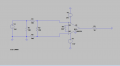
  • The AD8221 reads the differential signal directly from Pins 2 and 3.
  • The AD8221 reference and board supply are tied to AGND.
  • The board provides 15V (also referenced to AGND) across Pins 1 and 4.

Power Source (Pins 1/4)Connection of Pins 2/3Behavior
External 15VPins 2 & 3 floating (connected only to scope)Good — mV output as expected
External 15VPins 2 & 3 connected to board (AD8221 input)Good — mV output as expected
Board 15VPins 2 & 3 floating (connected only to scope)Good — mV output as expected
Board 15VPins 2 & 3 connected to board (AD8221 input)Bad — output jumps to several volts
Board 15VPins 1/4 to board, Pin 3 tied to Pin 4, Pin 2 floatingBad — output jumps to several volts
External 15VPin 4 tied to Pin 3, Pin 2 floatingBad — output jumps to several volts

What I Think Is Going On:
  • It seems to be some kind of grounding or common-mode reference issue.
  • The sensor behaves properly as long as its ground (Pin 4) is floating relative to the board.
  • When its ground gets tied to the board ground (either directly or indirectly via board power supply), the differential output shifts into volts instead of mV.
  • This makes me suspect:
    • Either a grounding architecture conflict.
    • Or that the sensor has internal active circuitry which doesn’t like how we're referencing it.

What I'm Hoping to figure out:
  • How can I definitively figure out whether the sensor is a passive Wheatstone or has active internal circuitry?
  • What exactly is likely causing these voltage shifts when tying grounds?
  • What design modifications could be made to fix the interface so this sensor behaves properly regardless of power source?
  • Would buffering the sensor output before connecting to the AD8221 solve this?
 

Attachments

ericgibbs

Joined Jan 29, 2010
21,390
hi dot,
Does the Black box sensor have any type label, if not what equipment was it recovered from, ie: what's it usage history.

E
 

Thread Starter

dotcomdotcom

Joined May 5, 2023
10
hi dot,
Does the Black box sensor have any type label, if not what equipment was it recovered from, ie: what's it usage history.

E
Not quite sure the history but it's the labeling is as follows:
Type: CPR820-5T-S06
Range: 0-5T
Output: 1.6 +- 0.005mV/V
Acc: 0.3%
Code: 202406W

It doesn't seem like the sensor is broken based on the tests I ran.
 

ericgibbs

Joined Jan 29, 2010
21,390
hi dot,
Searched for the CPR820 d/s no luck.
Checking your LTS asc simulation, the AD8221 cannot drive a 50R load.

I am trying various voltage supplies and grounding circuits.

As a test, have you measured the DC level out for the sensor with a range of supply voltages?
ie: Output: 1.6 +- 0.005mV/V
E
sim added
EG 1514.png
 

Attachments

Irving

Joined Jan 30, 2016
4,995
For what its worth, according to various Chinese websites, CPR820-5T-S06 is a flat panel 5 ton force sensor, manufactured by Shenzhen Keprui Sensor Co., Ltd. aka Cooperation Sensors (cprsensors.com), however they do not currently list that sensor in their online catalog. It seems to be part of a range of devices for weighbridges and the spec for what is listed as the matching CPR820 display unit suggests they are standard 350ohm Wheatstone bridges with a sensitivity between 0.4 and 6mV/V, with a suggested excitation voltage of 5v.

Personally I'd use an HX-711 load cell amplifier for this.
 
Last edited:

Thread Starter

dotcomdotcom

Joined May 5, 2023
10
hi dot,
Searched for the CPR820 d/s no luck.
Checking your LTS asc simulation, the AD8221 cannot drive a 50R load.

I am trying various voltage supplies and grounding circuits.

As a test, have you measured the DC level out for the sensor with a range of supply voltages?
ie: Output: 1.6 +- 0.005mV/V
E
sim added
View attachment 350371
HI Eric,
Thanks for taking the time to help me out and think this through.

After varying the supply input (pins 1 and 4) and connections I have found that the op-amp output saturates at 14.7V no matter what. The input of pins 2 and 3 will still vary to mV or V depending on the previously mentioned connections.
 

ericgibbs

Joined Jan 29, 2010
21,390
hi dot,
Using the External voltage supply, what voltage on points 2 and 3 [ not connected together or to any other point], what voltages do you measure from 2 and 3 to point 4?

If the sensor is a full bridge, I would expect it would be Vint/2 .

Repeat these voltage checks when using the Board supply.

Post your results.

E
 

KeithWalker

Joined Jul 10, 2017
3,603
If the sensor is a Wheatstone bridge arrangement, that is not how you show it in the sim diagram. Re: Connections shown in the AD8221 datasheet:
SGamp.jpg
But that still doesn't explain the odd behavior above!
 

MisterBill2

Joined Jan 23, 2018
27,159
If the sensor is an actual resistive or semiconductor bridge wired as shown in post #1, it is wired WRONG!!! THAT is an easy way to ruin a load cell by burning out one section.
Post #8 shows the correct way to connect a bridge type of load cell. PLEASE NOTE that the only connection to common allowed is for the excitation negative. BOTH outputs connect to the differential instrument amp inputs ONLY!
The information from the label as shown in post #3 describes a resistor bridge load cell.
The cheap trick to see if a package contains any active semiconductor devices is an external resistance check repeated with the polarity reversed. Semiconductors apparent resistance changes when the polarity is reversed, resistors do not change.
 

MisterBill2

Joined Jan 23, 2018
27,159
I have seen a $600 pressure transducer turned into an expensive door-stop by exactly that type of wrong connections.
The label data presented in post#3 explicitly defines the transducer as a bridge device.
 

Thread Starter

dotcomdotcom

Joined May 5, 2023
10
If the sensor is an actual resistive or semiconductor bridge wired as shown in post #1, it is wired WRONG!!! THAT is an easy way to ruin a load cell by burning out one section.
Post #8 shows the correct way to connect a bridge type of load cell. PLEASE NOTE that the only connection to common allowed is for the excitation negative. BOTH outputs connect to the differential instrument amp inputs ONLY!
The information from the label as shown in post #3 describes a resistor bridge load cell.
The cheap trick to see if a package contains any active semiconductor devices is an external resistance check repeated with the polarity reversed. Semiconductors apparent resistance changes when the polarity is reversed, resistors do not change.
Yes, I simulated it incorrectly and actually the real setup was post #8 from Keith's. The issue has been resolved as we had a resistor go to AGND from the inverting side due to the board being compatible for different types of sensors so the board was printed with the resistor for another sensor type. Thanks for all the help everyone
 
Last edited:

MisterBill2

Joined Jan 23, 2018
27,159
That on-board single resistor is sometimes a "bridge completion resistor," used so that single resistor sensors can be used conveniently.
 
Top