Facebook
 Google
 GitHub
 Linkedin
Hi group
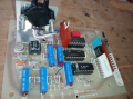
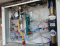
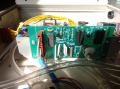
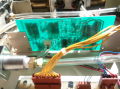
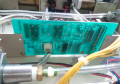
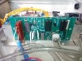
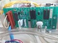
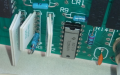
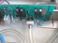
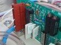
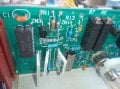
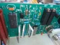
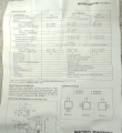
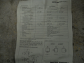
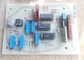
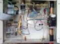
This is a pressure sensor signal modulation board.(Please see the attached "PCB" file.)
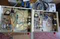
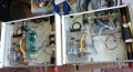
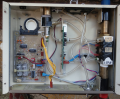
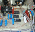
It comes from inside the flow module.(Please see the attached image "PCB3".)
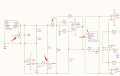
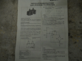
I have drawn the schematic diagram of the actual PCB. Please see the attached "Schematic diagram - Full version".
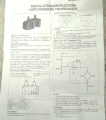
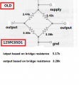
The pressure sensor 125PC05D1 is used in conjunction with this signal conditioning board.The pressure sensor 125PC05D1 operates at a voltage of 0-10VDC and a current of 0-2mA.Input or output impedance approximately 5K ohms.
The 125PC05D1 pressure sensor exhibits severe zero-point drift.So I had no choice but to replace it.
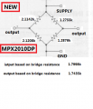
I've decided to try replacing the 125PC05D1 with an MPX2010DP pressure sensor. The MPX2010DP pressure sensor operates at 10V and draws 6mA. Its input impedance is 1.7998K ohms, and its output impedance is 1.7435K ohms.
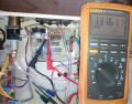
R1123(VB SET):Used to adjust the bias voltage, which is the operating voltage of the pressure sensor V+ and V- (typically 10,000V).
R1116(ZERO):Used to adjust the voltage between S+ and GND or between S- and GND to 0.000V.
R1111(XDBAL):Used to adjust the voltage between S+ and S- to 0.000V.
R1102(NULL):Used to adjust the Vout (HI-LO voltage)output voltage to 0 ± 0.005Vdc(Adjust according to the requirements in the service manual.)
R1109(TC):No adjustments have been made yet; it appears to be used to adjust temperature drift compensation, but it's unclear exactly how to adjust it.
Since the original pressure sensor signal modulation board used a 125PC05D1 pressure sensor, and I have now replaced it with an MPX2010DP pressure sensor, how should I modify the original signal modulation board to make the MPX2010DP pressure sensor work properly? Furthermore, how should I configure the bias circuit, zero-adjustment circuit, differential amplifier circuit, gain circuit, etc., to meet the original parameter requirements?
Another question is, how can we keep the Vout output voltage constant (in the zero-pressure input state)?
https://i.postimg.cc/9FsYrnXF/sensor-125pc05d1.jpg
https://i.postimg.cc/02h0bB5r/sensor-125pc05d1-2.jpg
This is a pressure sensor signal modulation board.(Please see the attached "PCB" file.)
It comes from inside the flow module.(Please see the attached image "PCB3".)
I have drawn the schematic diagram of the actual PCB. Please see the attached "Schematic diagram - Full version".
The pressure sensor 125PC05D1 is used in conjunction with this signal conditioning board.The pressure sensor 125PC05D1 operates at a voltage of 0-10VDC and a current of 0-2mA.Input or output impedance approximately 5K ohms.
The 125PC05D1 pressure sensor exhibits severe zero-point drift.So I had no choice but to replace it.
I've decided to try replacing the 125PC05D1 with an MPX2010DP pressure sensor. The MPX2010DP pressure sensor operates at 10V and draws 6mA. Its input impedance is 1.7998K ohms, and its output impedance is 1.7435K ohms.
R1123(VB SET):Used to adjust the bias voltage, which is the operating voltage of the pressure sensor V+ and V- (typically 10,000V).
R1116(ZERO):Used to adjust the voltage between S+ and GND or between S- and GND to 0.000V.
R1111(XDBAL):Used to adjust the voltage between S+ and S- to 0.000V.
R1102(NULL):Used to adjust the Vout (HI-LO voltage)output voltage to 0 ± 0.005Vdc(Adjust according to the requirements in the service manual.)
R1109(TC):No adjustments have been made yet; it appears to be used to adjust temperature drift compensation, but it's unclear exactly how to adjust it.
Since the original pressure sensor signal modulation board used a 125PC05D1 pressure sensor, and I have now replaced it with an MPX2010DP pressure sensor, how should I modify the original signal modulation board to make the MPX2010DP pressure sensor work properly? Furthermore, how should I configure the bias circuit, zero-adjustment circuit, differential amplifier circuit, gain circuit, etc., to meet the original parameter requirements?
Another question is, how can we keep the Vout output voltage constant (in the zero-pressure input state)?
https://i.postimg.cc/9FsYrnXF/sensor-125pc05d1.jpg
https://i.postimg.cc/02h0bB5r/sensor-125pc05d1-2.jpg
Attachments
-
 1.5 MB Views: 5
 -
 1.5 MB Views: 6
 -
 767.4 KB Views: 7
 -
677.7 KB Views: 0
-
 205.7 KB Views: 7
 -
 212.1 KB Views: 7
 -
 136.9 KB Views: 6
 -
 46.8 KB Views: 6
 -
 46.3 KB Views: 5
 -
137.5 KB Views: 4
Last edited: