 Facebook
 Google
 GitHub
 Linkedin
Howdy,
It's my first post here, I've been trying to work the issue out myself, but where I'm at currently I've no functioning RDA protection on the mains breaker and I've no sacrificial fuse equipped power bar to plug my project into in case it causes a surge
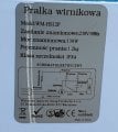
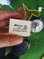
I'm trying to fix my grandma's old portable -mini washing machine, it has been working with a broken timer switch for quite a while. It was ingenious enough to operate on a gear mechanism that would engage and disengage electrical contact plates when the timer was on and would turn off automatically. couple o years back the timer function started malfunctioning, and the machine kept going all the time when it was plugged. then it stopped working altogether. I identified the culprit in a broken contact pad that stopped the electricity from flowing into the motor and prevented it from running. I quickly decided to rebuild the circuit with the exclusion of a timer, and inclusion of an ac switch on the power cord (don't worry, I checked the rating). Now, I know, from my limited knowledge of motor wiring, that the motor used in this circuit is a one-phase dc motor with a start capacitor and that's all fine, but there is another smaller component that seems like a capacitor and resistor combo? since it's got a voltage, a capacitance, and a resistance rating. it also has 3 wire terminals as opposed to just 2 I'm used to on capacitors. That's where I am completely lost, as I don't know how to wire each capacitor to one another and how to connect the motor in series. This is just too much for my beginner's electronics knowledge, and the diagram is not helping! i see 3 capacitors on the diagram, and i do not know which is which, as well as a fuse that was never there, to begin with ( perhaps it is in the 3 lead combo unit?)
Please help me work this out.
The components I have for are:
- a 50watt dc single phase motor with 3 wires - yellow, red, and blue (blue being neutral and red, I assume, is the one used for the start winding, but i could be wrong)
- a 4 micro Farrad start capacitor rated for 450 volts
- a grounded 3 wire cable with an AC on/off switch
- a component that I can't fully identify and find a use for in the circuit with the name TNS - 2 40/085/21/C GB/T14472
( online i found a variable switch circuit using this component
- a housing and a belt
.
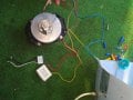
Here are the pictures of the components as well as the diagram, and the picture showing how I've connected the components
i attached the diagram with my markings of the wires and color coding as well as with an x over the part of the circuit thats gone bad and I want to circumvent
It's my first post here, I've been trying to work the issue out myself, but where I'm at currently I've no functioning RDA protection on the mains breaker and I've no sacrificial fuse equipped power bar to plug my project into in case it causes a surge
I'm trying to fix my grandma's old portable -mini washing machine, it has been working with a broken timer switch for quite a while. It was ingenious enough to operate on a gear mechanism that would engage and disengage electrical contact plates when the timer was on and would turn off automatically. couple o years back the timer function started malfunctioning, and the machine kept going all the time when it was plugged. then it stopped working altogether. I identified the culprit in a broken contact pad that stopped the electricity from flowing into the motor and prevented it from running. I quickly decided to rebuild the circuit with the exclusion of a timer, and inclusion of an ac switch on the power cord (don't worry, I checked the rating). Now, I know, from my limited knowledge of motor wiring, that the motor used in this circuit is a one-phase dc motor with a start capacitor and that's all fine, but there is another smaller component that seems like a capacitor and resistor combo? since it's got a voltage, a capacitance, and a resistance rating. it also has 3 wire terminals as opposed to just 2 I'm used to on capacitors. That's where I am completely lost, as I don't know how to wire each capacitor to one another and how to connect the motor in series. This is just too much for my beginner's electronics knowledge, and the diagram is not helping! i see 3 capacitors on the diagram, and i do not know which is which, as well as a fuse that was never there, to begin with ( perhaps it is in the 3 lead combo unit?)
Please help me work this out.
The components I have for are:
- a 50watt dc single phase motor with 3 wires - yellow, red, and blue (blue being neutral and red, I assume, is the one used for the start winding, but i could be wrong)
- a 4 micro Farrad start capacitor rated for 450 volts
- a grounded 3 wire cable with an AC on/off switch
- a component that I can't fully identify and find a use for in the circuit with the name TNS - 2 40/085/21/C GB/T14472
( online i found a variable switch circuit using this component
- a housing and a belt
.
Here are the pictures of the components as well as the diagram, and the picture showing how I've connected the components
i attached the diagram with my markings of the wires and color coding as well as with an x over the part of the circuit thats gone bad and I want to circumvent
Attachments
-
 157.6 KB Views: 9
 -
 135.6 KB Views: 9
 -
 2.2 MB Views: 9
 -
 869.1 KB Views: 8


