Polarity controlled relay output

Thread Starter

offgridcircuits

Joined Mar 12, 2024
18
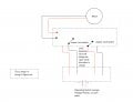
I am looking for a simple circuit. I think it's simple. I believe a DPDT relay will be involved but I cannot figure out the polarity.
I have a motor that can reverse on polarity. I need the + or - input to the motor to trigger voltage to select one of two circuits to be energized. For Example, a positive DC voltage triggers output 1 and a negative DC voltage (reversed) triggers output 2. This is due to the motor's limit switches that open the circuit in one direction until an opposite polarity starts it in the opposite direction.
Any help would be appreciated. This is about < 2A @ 12V
 

geekoftheweek

Joined Oct 6, 2013
1,429
Connect the relay coil to the '+' of your motor and to your power supply "ground". The relay will only energize in one direction. Do not connect the relay coil to the '+' and '-' of the motor otherwise the relay will most likely always be energized since they will work in either direction normally... the exception is if there is a diode built in to the relay.
 

Thread Starter

offgridcircuits

Joined Mar 12, 2024
18
Connect the relay coil to the '+' of your motor and to your power supply "ground". The relay will only energize in one direction. Do not connect the relay coil to the '+' and '-' of the motor otherwise the relay will most likely always be energized since they will work in either direction normally... the exception is if there is a diode built in to the relay.
Not sure I understand how this would work. How would a + voltage select one throw of the relay and an - voltage select an opposite throw of the dpdt relay?
 

crutschow

Joined Mar 14, 2008
38,325
You can use two SPDT relays to form a H-bridge, which can reverse the polarity to the motor leads.
Do you want the motor to stop when there's no control signal?
If not, then one DPDT relay should work, which requires only one signal.
 

Thread Starter

offgridcircuits

Joined Mar 12, 2024
18
You can use two SPDT relays to form a H-bridge, which can reverse the polarity to the motor leads.
Do you want the motor to stop when there's no control signal?
Yes, I need the motor to stop when the limit switches cut off the voltage. There are two limit switches. One for direction A and One for Direction B. Once Limit switch A is reached that circuit is dead. So the circuit on Limit switch B has to be energized with a reverse polarity to get the motor to run in the opposite direction until that limit is reached and so forth.
 
Last edited:

Thread Starter

offgridcircuits

Joined Mar 12, 2024
18
Yes, I need the motor to stop when the limit switches cut off the voltage. There are two limit switches. One for direction A and One for Direction B. Once Limit switch A is reached that circuit is dead. So the circuit on Limit switch B has to be energized with a reverse polarity to get the motor to run in the opposite direction until that limit is reached and so forth.
To simplify, I have a control switch that reverses polarity of a circuit to a motor. The switch runs the motor until the limit switch is reached, which opens that circuit. So I reverse polarity of the control switch and the motor reverses on a separate circuit and then until the opposite direction limit switch is reached which opens that circuit.
 

Thread Starter

offgridcircuits

Joined Mar 12, 2024
18
Can you post a schematic of that switch and motor connection?
Here is my understanding of the circuit. I'm retrofitting an RV fan Lid switch to work with a newer fan that is wired different than the original. I cannot change the switching to the fan (the reversing polarity to the fan to operate the lid up/down) so this is what I have to work with. My problem is the limit switches that need to cut the circuit when the lid is down or all the way up.
 

Attachments

crutschow

Joined Mar 14, 2008
38,325
I'm retrofitting an RV fan Lid switch to work with a newer fan that is wired different than the original.
How is the new fan different from the old?
We need all the information, about what you are doing not just some.

Still not clear.
So it would seem that you reverse the polarity to operate the lid, but the fan stops when the polarity to close the lid is applied?
 

Thread Starter

offgridcircuits

Joined Mar 12, 2024
18
How is the new fan different from the old?
We need all the information, about what you are doing not just some.

Still not clear.
So it would seem that you reverse the polarity to operate the lid, but the fan stops when the polarity to close the lid is applied?
The old lid did not have limit switches. The new one does. So, I'm trying to incorporate the open limit and closed limit switches in the circuit. The new fan lid is really two circuits. An open circuit to the lid with a limit. And a closed circuit to the lid with a limit, when all the way closed. I'm sorry if I'm not explaining it properly. It appears the original OPEN/CLOSED switch is a spdt switch that reverses polarity to the lid cover. Each activation of the switch causes the polarity to reverse. I cannot change this logic of the operating switch and want it to work as original.
 

Thread Starter

offgridcircuits

Joined Mar 12, 2024
18
Sorry, but how can the circuit work if it's an open circuit?
Please explain exactly how the new fan and circuit work.
Is all the power to the fan and lid coming from the switch?
I confused you. the Opening Signal and Closing signal are a reversed polarity voltage. Not an open circuit. I'm sorry about the confusion.
 

geekoftheweek

Joined Oct 6, 2013
1,429
Not sure I understand how this would work. How would a + voltage select one throw of the relay and an - voltage select an opposite throw of the dpdt relay?
I think I misunderstood what you are trying to do.

If I am imagining things right you want it positive is applied to '+' it will trigger the relay one way, and when positive power is applied to the '-' it will trigger the relay the other way, and with no power it is off. Simply put a relay will not work that way.

What I suggested would make it so the NO contacts would close when positive power is applied to '+', but all other times the NC contacts would be closed.

Do you have any part numbers?
 

Thread Starter

offgridcircuits

Joined Mar 12, 2024
18
I think I misunderstood what you are trying to do.

If I am imagining things right you want it positive is applied to '+' it will trigger the relay one way, and when positive power is applied to the '-' it will trigger the relay the other way, and with no power it is off. Simply put a relay will not work that way.

What I suggested would make it so the NO contacts would close when positive power is applied to '+', but all other times the NC contacts would be closed.

Do you have any part numbers?
I do not. I have drawn this out with relays and cannot get the logic to work. The issue is that once a limit switch is reached in the mechanical travel, the circuit opens and no voltage, + or - can reach the motor. this was originally microprocessor controlled in the fan housing circuit, but that is now disabled.
 

crutschow

Joined Mar 14, 2008
38,325
Can you power the fan from the control signal?
If so, just wire the fan to the switch output that has a voltage when the open (to the upper limit switch) signal is sent.
 

Thread Starter

offgridcircuits

Joined Mar 12, 2024
18
Can you power the fan from the control signal?
If so, just wire the fan to the switch output that has a voltage when the open (to the upper limit switch) signal is sent.
What I have determined is that a dpdt relay will do the switching, but my problem is the signal to the relay. It's on a button switch that on one push and hold, it sends a positive voltage to the circuit, which will activate the relay. On the subsequent push and hold ,it reverses polarity (so the vent cover motor will reverse and close). That is the problem. The polarity reversal and I cannot change that or I do not know how to. I might just have to buy a new fan.
 

crutschow

Joined Mar 14, 2008
38,325
What I have determined is that a dpdt relay will do the switching
Why are you locked in to that when you don't know how it will work?
What is you basis for that determination?
If you ignore my questions to further explain what you have, because that's still far from clear, I can't help you.
It's on a button switch that on one push and hold, it sends a positive voltage to the circuit
Does that generate a momentary or steady signal?
 

Thread Starter

offgridcircuits

Joined Mar 12, 2024
18
Why are you locked in to that when you don't know how it will work?
What is you basis for that determination?

From diagrams I have seen on the web is all I can determine. I'm open to ideas. Maybe a solenoid that engages-operates two different circuits. One is Lid up and the other is lid down.

If you ignore my questions to further explain what you have, because that's still far from clear, I can't help you.
Does that generate a momentary or steady signal?

It generates a steady signal/voltage for as long as it's activated/pushed. Once released, it is zero or open. Then, when pressed again, it is the opposite polarity for as long as you hold the switch.
 

crutschow

Joined Mar 14, 2008
38,325
It generates a steady signal/voltage for as long as it's activated/pushed. Once released, it is zero or open. Then, when pressed again, it is the opposite polarity for as long as you hold the switch.
Okay it would seem you could use a DPDT latching relay, such as one of these.

But until I understand exactly how the switch connections, and lid and fan would work without the microprocessor, I don't really know how to connect it.
Can you tell me exactly what signals you now need to the fan and to the lid for their proper operation.
That would be a great help.
 

Thread Starter

offgridcircuits

Joined Mar 12, 2024
18
Thanks for that latching relay. it's interesting and I'll have to study that more.

What I'm working with, in simple terms, is a switch to activate the circuit. I cannot change this switch. It changes polarity to the fan location with each activation. I also have a motor in the fan for the fan lid that is DC and can reverse direction on polarity for the up and down action. And I have two limit switches at the fan lid that are NC until the lid opens them. I can wire it any way that is necessary, but that is all I'm working with, so far.
 
Top