 Facebook
 Google
 GitHub
 Linkedin
Hi all,
I'm working on a circuit for a motorsport application and wanted to get some eyes on it before I build it. I'd appreciate any feedback on whether this will work as intended or if I've missed anything.
**The Goal**
I have a motor controller that outputs ~12–15V (automotive battery voltage) and reverses polarity as a control signal. I want to use that polarity reversal to switch between two DC-DC converters — a 24V and a 16V — feeding a single output load rated at up to 40A.
- Polarity + → 24V converter connects to output
- Polarity − → 16V converter connects to output
- Only one supply should ever be connected at a time
**The Circuit**
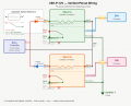
I'm using two identical Panasonic CB1-P-12V relays (12V coil, 40A SPDT).
Each relay coil is driven from the motor controller output via a 1N5404 diode in series — one diode forward, one reversed — so each relay only activates on one polarity.
A 1N5404 flyback diode is placed across each coil (cathode toward Pin 1 / controller side) to protect the controller from inductive spikes.
On the contact side, Pin 4 (COM) on each relay is fed from its respective converter through a 40A fuse. Pin 2 (NO) on both relays joins together at the output. Pin 3 (NC) is left unconnected on both.
All grounds — controller negative, both converter negatives, and load negative — share a common ground point.
---
I guess my question is to see if there is something alarming that I am not thinking about, or any recommendations anyone could give.
Thanks in advance!

I'm working on a circuit for a motorsport application and wanted to get some eyes on it before I build it. I'd appreciate any feedback on whether this will work as intended or if I've missed anything.
**The Goal**
I have a motor controller that outputs ~12–15V (automotive battery voltage) and reverses polarity as a control signal. I want to use that polarity reversal to switch between two DC-DC converters — a 24V and a 16V — feeding a single output load rated at up to 40A.
- Polarity + → 24V converter connects to output
- Polarity − → 16V converter connects to output
- Only one supply should ever be connected at a time
**The Circuit**
I'm using two identical Panasonic CB1-P-12V relays (12V coil, 40A SPDT).
Each relay coil is driven from the motor controller output via a 1N5404 diode in series — one diode forward, one reversed — so each relay only activates on one polarity.
A 1N5404 flyback diode is placed across each coil (cathode toward Pin 1 / controller side) to protect the controller from inductive spikes.
On the contact side, Pin 4 (COM) on each relay is fed from its respective converter through a 40A fuse. Pin 2 (NO) on both relays joins together at the output. Pin 3 (NC) is left unconnected on both.
All grounds — controller negative, both converter negatives, and load negative — share a common ground point.
---
I guess my question is to see if there is something alarming that I am not thinking about, or any recommendations anyone could give.
Thanks in advance!
Attachments
-
 62.3 KB Views: 0


