Opposing polarity caps?

Thread Starter

metermannd

Joined Oct 25, 2020
472
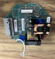
Got my hands on another board long enough to get enough pictures to reverse engineer it.

Just want to throw this out there and see what the knowledge base here thinks... look at C2 and C3. It sure looks like they are hooked up in opposing polarities?

Also attached is the schematic i've worked out of the board - it's a power supply / relay board for a load control receiver.
 

Attachments

meth

Joined May 21, 2016
298
Do you have the capacitors C3 and C5? Or you got the board like that?
Because I don't think they are electrolyte capacitors.
 

sagor

Joined Mar 10, 2019
1,046
I suspect C3 is a bypass capacitor. Why they show a "+" on the silkscreen may be some artifact left over from the design software. C2 is the only electrolytic cap, and its "+" sign is much bigger than the rest.
If this turns out to be an AC supply (no rectifier diodes), then C2 and C3 would not be installed. Output would be on AC1 and AC2, there would be no "DC" output
 

Thread Starter

metermannd

Joined Oct 25, 2020
472
I think sagor's reasoning might be the closest to what I'm seeing.

This board could be populated in a few different ways depending on the specific application... there are other boards within this system that had parts or pads thereof that were normally unpopulated, but the boards were never redone to remove options that nobody ever ordered.

My guess is that the capacitors and diode bridge only saw use in 'remote relay box' applications and the resistor vs jumper allowed the use of 5V relays instead of standard 12V relays.
 

Tonyr1084

Joined Sep 24, 2015
9,744
You CAN use two electrolytic caps back to back to form a non-polarity specific capacitor. Here's a picture.
Image deleted.
 
Last edited:
Top