PNP state not acting according to wikipedia

Thread Starter

yef smith

Joined Aug 2, 2020
1,454
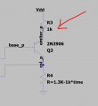
Hello , As a side issue my PNP is not acting like in wikipedia.
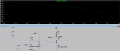
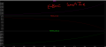
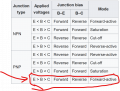
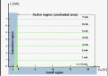
photos 1 to 5 represent a state where E>B>C which acctording to wikipedia its supposed to be a high current state called forward active.
but instead I get the opposite very weak current as if I am at saturation.
Where did I go wrong?
LTspice file is attached.
Thanks.
 

Attachments

Thread Starter

yef smith

Joined Aug 2, 2020
1,454
Hello , I am in active region but the emiter resistor is limiting the current.
How Is the resistor limiting exactly ? what is the mathematical logic of this resistor limiting the PNP?
LTspice file is attached.
Thanks.
 

Attachments

Thread Starter

yef smith

Joined Aug 2, 2020
1,454
Yes ohms law says how much voltage we will have on the emitter.I want to stay in the active region so my Veb must increase .
I reduced R3 to 1 ohm and I_E stays the same.
1742574466177.png
 

Papabravo

Joined Feb 24, 2006
22,072
The following simulation shows the result of controlling only the base current. All of the node voltages are derived from the value of the base current. This is as it should be.

1742582119656.png

R1 sets the emitter current limit at 9V/332 Ω ≈ 27 mA.
 

Attachments

Last edited:

Papabravo

Joined Feb 24, 2006
22,072
No it’s from a youtube video .
And perhaps of dubious parentage as well. For the third time I'm asking you to explain the purpose of the circuit. If you won't or can't comply with this request, you are on your own and I will be unable to offer further assistance.
 

tonyStewart

Joined May 8, 2012
231
Contrary to what @Papabravo indicated, BJTs are Vbe voltage controlled Ic-current sinks. They are linearized by adding an emitter R so that the voltage rise in Vbe is an Ohms Law function of the emitter R but limited also by the Thevenin equivalent of the voltage source to the base. The resulting base current controls Vbe which in turn controls Ic. But because of the log function of Ib to Vbe and Vbe to Ic with a significant Re much greater than re internal, there is a quasi linear current gain function. Although hFE has a notorious wide dynamic range, it is still very useful to estimate Iq in standard configurations. Except when saturated hFE drops to about <=10% of its max linear hFE So OEM’s will specify it at a fixed ratio like Vce(sat) =o.xx at Ic/Ib=10 or 20 or 50.

This is Ic vs Vbe is logarithmic characteristic until either Ic or Ib becomes saturated or where excess voltage drop on Rc causes B-C to shunt B-E and the difference becomes Vce(sat). In that state the current source becomes a switch with a series R = Rce=Vce(sat)/Ic where you can now estimate linear switch rise with current.

Veb in the PNP is limited in the base current from being starved by the left side differential driver because the PNP’s collector R voltage rise pulls up the right side base-emitter voltage to cause its collector current to consume almost all of the current in the 80 Ohm resistor.

In this case the PNP is almost cutoff, yet its collector rise in voltage is enough to force the right side non-inverting input to hog most of the current in the diff. pair.

There is no obvious application for this NFB circuit.
 
Last edited:

nsaspook

Joined Aug 27, 2009
16,275
The solid state physics says they are voltage controlled current devices (electric field across the base-emitter junction decreases the width of the depletion zone) the engineering model is usually that of a current controlled device for large signal operation (switching) because those equations are simpler for good approximations of practical circuits. For the small signal/linear realm, voltage models provide better approximations in most cases.

https://circuitcellar.com/resources/quickbits/the-ebers-moll-bjt-model/
The Ebers-Moll BJT Model
 
Last edited:
Top