Facebook
 Google
 GitHub
 Linkedin
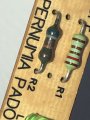
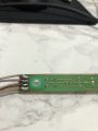
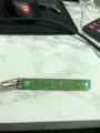
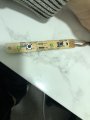
This is Genius... Makes complete sense.post good photos of the PCB front and back so we can check how they are connected. also check if there is a break in PCB tracks if the PCB was bent (button pressed too hard). that would explain your workaround where you are pressing on the bottom side of the board (tracks side). this bends the board back and broken tracks make the contact. the same would happen if resistor is not soldered correctly (cold joint). this is fixed by touching up all pads with soldering iron. broken tracks can be cured by adding wire in parallel (connecting pads that are on same track).
View attachment 286071
As the Resistor is in the middle of the board, providing the most flex.
What sort of wire should I use?
I can't see anything obvious with a magnifying glass.
Pictures below.
Thanks
Attachments
-
 119 KB Views: 10
 -
 132.1 KB Views: 10
 -
 130.1 KB Views: 10
 -
 147.5 KB Views: 9