
 Facebook
 Google
 GitHub
 Linkedin

Back in 1980, Hitachi briefly experimented with a "Super linear ckt" design". I'm only aware of its use in two low-power integrated amp models, HA4700 (50 w/ch) and HA3700 (35 w/ch). (FYI: I am currently servicing an HA4700 which, with a prev. owner, suffered some damage in the R channel pwr amp stage. The L. ch is okay.)
The design goal seems to have been to "super linearize" the top (+) and bottom (-) half of the waveform to minimize switching (crossover) distortion. The serv manual goes into some of the theory.
It is a unique design that Hitachi didn't use long because of difficulty in controlling/stabilizing oscillation and biasing issues.
The full 27-page service manual is here:
https://archive.org/details/manual_HA4700_HITACHI/page/n1/mode/2up
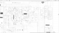
This attached screen capture is from the HA4700 serv. manual schematic. It shows just the pwr amp section of one (L) channel.
Note Q715L (2SC1775A) after the two output pwr transistors (Q714/715) . Q715L is in the signal path (right-pointing arrow) and is in ckt just before the protection relay.
Anyone know what Q715L (2SC1775A) does?
The design goal seems to have been to "super linearize" the top (+) and bottom (-) half of the waveform to minimize switching (crossover) distortion. The serv manual goes into some of the theory.
It is a unique design that Hitachi didn't use long because of difficulty in controlling/stabilizing oscillation and biasing issues.
The full 27-page service manual is here:
https://archive.org/details/manual_HA4700_HITACHI/page/n1/mode/2up
This attached screen capture is from the HA4700 serv. manual schematic. It shows just the pwr amp section of one (L) channel.
Note Q715L (2SC1775A) after the two output pwr transistors (Q714/715) . Q715L is in the signal path (right-pointing arrow) and is in ckt just before the protection relay.
Anyone know what Q715L (2SC1775A) does?
Attachments
-
 1.1 MB Views: 22
Last edited:




