Please help clarifying Optical Compressor PCB connections

Thread Starter

sonohe

Joined Jan 11, 2025
91
I want to draw the schematic of the Carl Martin Optocomp to be able to modify it later to make it better suit to my needs.

I managed to desolder every part successfully. I have some problems with understanding the connections here and there. Especially at the input jack and the power inputs.

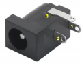
So this is how the input jack slot looks. Why is it a 3 pole jack? I don't understand that. Why not just mono? The PSU barrel plug slot is also 3 pole. Here is the photo of that too:
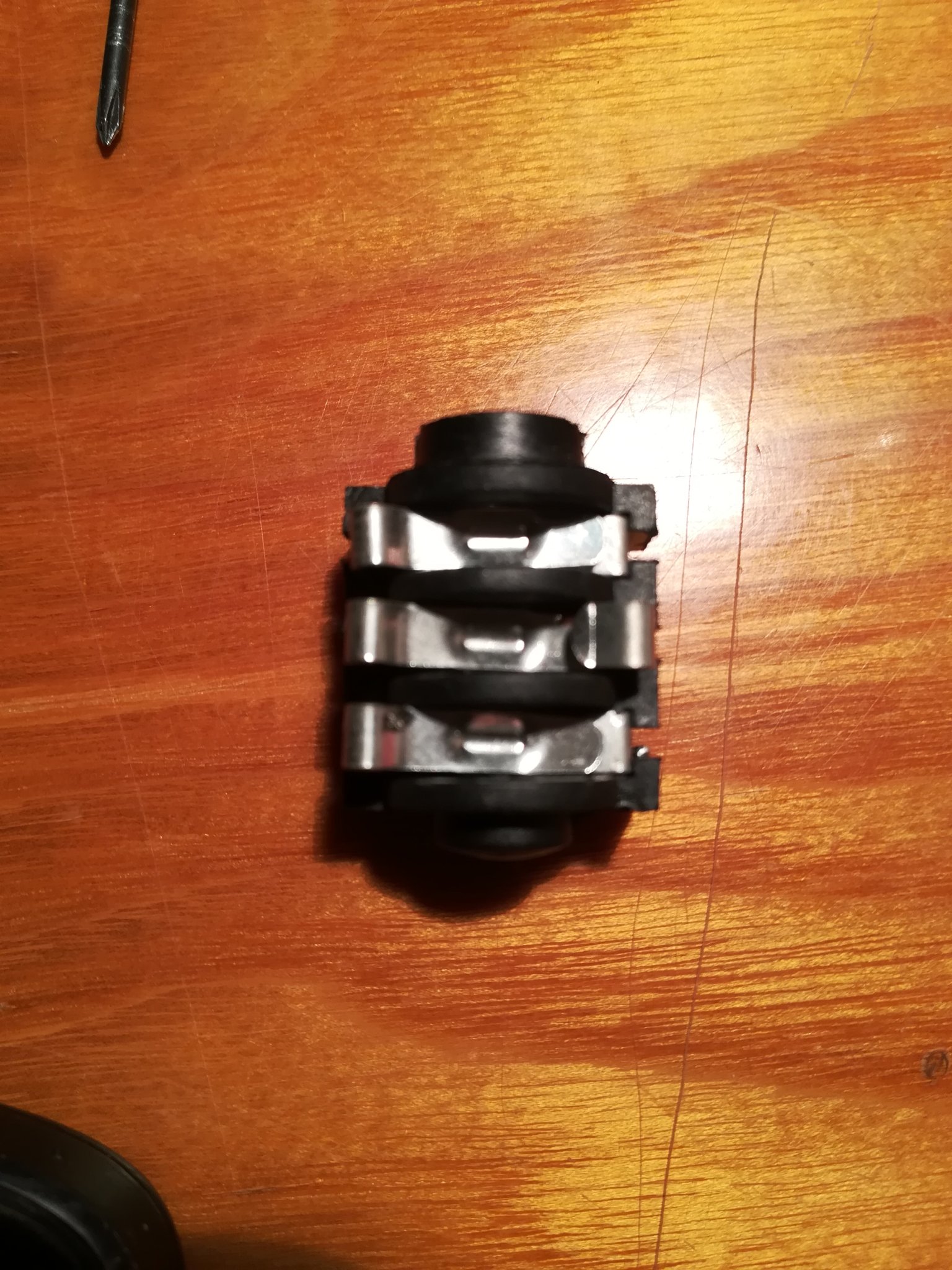
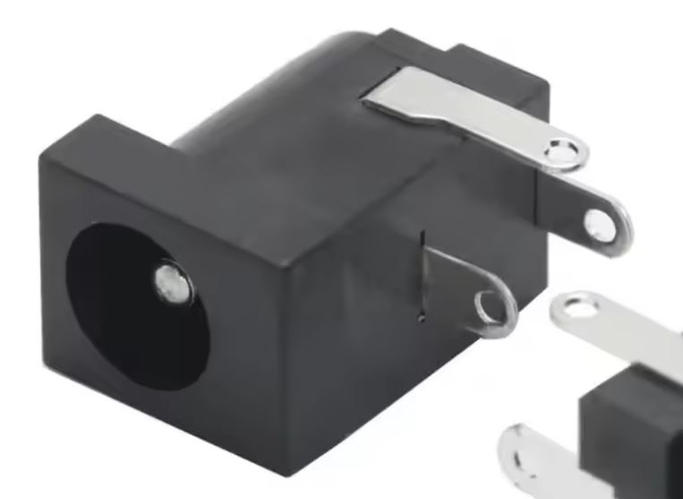
IMG_20260709_034214.jpg


aljzat.JPG


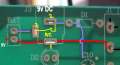
This is how the connections look in that input area. I don't really get what's the role of the additional +1 pole on these slots:
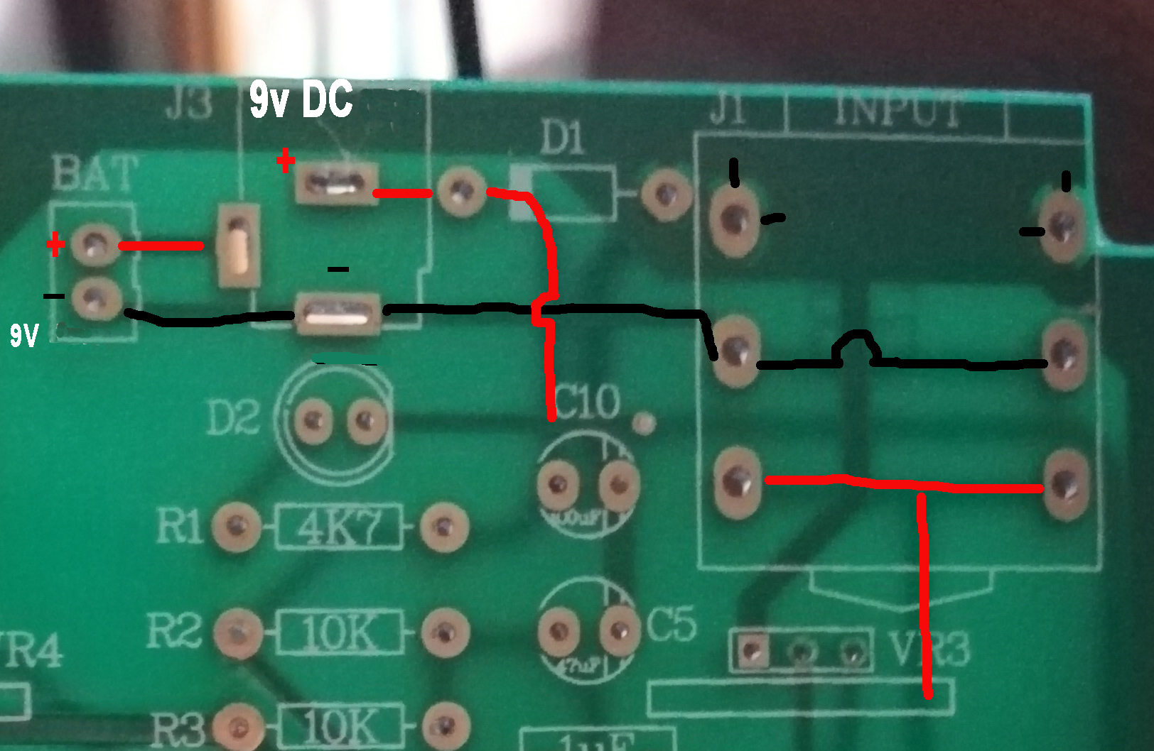
Input környéke en.jpg
 

Thread Starter

sonohe

Joined Jan 11, 2025
91
two of the three contacts are switch. it changes state depending on if jack is plugged in or not. this allows selecting power source (battery/psu).
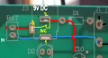
Thanks, however, there is something I still don't understand. On the jack input slot you have the upper 2 legs (connected directly to ground), the middle two (that connects through the black route to the black cable of the battery), and the lower two that is the red route (signal).

But the black cable of the battery should connect to the ground rail as well. Where is that connection? Because these are all the traces I drew in that area. Based on what you wrote it is the jack plug sleeve that connects the upper and middle connection points in the jack slot right? So you plug in the jack, and that completes the flow in the black route in the circuit, so it goes like: battery black -> middle connection point in jack slot -> jack sleeve -> upper connection point in jack slot -> ground rail, right?
 

panic mode

Joined Oct 10, 2011
5,099
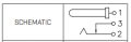
for any communication to take place, things need to be labeled and datasheet linked. so how about this:

1783602037677.png

see the BOTTOM of the above picture?

pin1 is crimped to the center stud.
pin2 is ring.
pin3 is normally closed contact (2-3) meant for non-rechargeable batteries. when plug is inserted, pi3 is disconnected and device is onyl powered by external power supply.

on your connector that looks like this
1783601976235.png


and usually center is positive so tour picture is probably more like this:

1783602383555.png
 
Last edited:

Thread Starter

sonohe

Joined Jan 11, 2025
91
for any communication to take place, things need to be labeled and datasheet linked. so how about this:

View attachment 369283
View attachment 369282

pin1 is crimped to the center stud. and usually center is positive.
pin2 is ring.
pin3 is normally closed contact (2-3)
I think some essential info is missing: in guitar pedals the DC plug is tip negative. What you drew as red on the battery connector is actually black in reality. I know because I noted it when I desoldered the board components. So the colors go as I drew it. The black route is as you see on my image.
 

Thread Starter

sonohe

Joined Jan 11, 2025
91
i said usually.... not always. i am not familiar with that product so it may as well be one where center pin is negative.
do you understand function of pin3 now?
Absolutely. May I ask that can you link or paste a photo of how you need to draw these 3 pole jack and barell plug sockets into the schematic? I want to draw these correctly but I am not familiar with how you need to draw them in this particular situation.

And how do you call these type of sockets? I guess the jack socket is simple stereo socket isn't it? With one channel used as negative source and a switch. But how do you find the barell socket that can be used like here, as a switch? Simply 3 pole DC socket?
 
Top