Please help me reverse engineer this PCB.

Thread Starter

Failer

Joined Jul 11, 2009
27
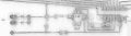
This is a power sequencer design by my late father many years ago. I found the remaining PCBs in a drawer but the notes and schematics are long gone. I was hoping someone could reverse-engineer it and help me to determine the components and values.

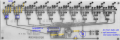
It is built around the LM3914 driver which go to optocouplers, then triacs for the power side. The driver input is just fed with a RC to provide a voltage ramp up for it to read. I'm not really clear on what the exact arrangement of components is here. Conceptually simple, but I don't know how to actually choose any of the components.

Also, the outputs of the optocouplers, that section gets a little confusing, I'm not really sure what would go where for any of those traces, I have put highlights there but I don't know if they are correct. Maybe gate resistors? TBH, I feel like it would be easier for me to use the driver outputs to drive SSRs directly, but that's likely considerably more expensive and I think I already have most of these components already. Plus, I'm trying to learn here.

Can anyone assist? Begin by assuming that I know nothing about electronics. I know some, but I don't have enough for it to be useful without assistance.

I have reversed the picture here so that I could consider the design a little easier wrt to the pin locations.
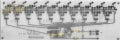
IMG_20260912_0001.jpg
 

Ian0

Joined Aug 7, 2020
13,264
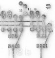
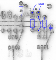
I would guess that 1k, 39 and 51 refer to resistor values; and that the optos are MOC3042s, and that C is actually an LED because if it were a capacitor there couldn't be any continuous current through the opto. T1 and G refer to the triac's MT1 and Gate terminals, MT2 is the tab which is connected to a live heatsink and the live is connected to the upper of the two tracks that go under the resistors. J is a jumper.
So when the opto is gated on it connects MT2 (which is live) to gate via the 51Ω resistor triggering the triac. The unlabelled component in the group would be a capacitor which forms a snubber with the 39Ω resistor, although the capacitor appears too small to be a class-x safety capacitor. 1k is a gate-MT1 resistor which pulls the gate down to ensure it isn't triggered by interference.
 

Thread Starter

Failer

Joined Jul 11, 2009
27
hi F,
Cleaned up two sections of your image, make it easier to read.
What type are the Opto's?
Couldn't say, that's why I'm here. I think there may be some spare parts around , so I can look and see if there are any that look like they were used here. I wouldn't be able to do that until tonight or tomorrow. I doubt they were anything unique, my father was all about simplicity, and frankly, a cheapskate, so I doubt they are anything exotic. Think along these lines, what would have been a common one in 1980?
 

Thread Starter

Failer

Joined Jul 11, 2009
27
I would guess that 1k, 39 and 51 refer to resistor values; and that the optos are MOC3042s, and that C is actually an LED because if it were a capacitor there couldn't be any continuous current through the opto. T1 and G refer to the triac's MT1 and Gate terminals, MT2 is the tab which is connected to a live heatsink and the live is connected to the upper of the two tracks that go under the resistors. J is a jumper.
So when the opto is gated on it connects MT2 (which is live) to gate via the 51Ω resistor triggering the triac. The unlabelled component in the group would be a capacitor which forms a snubber with the 39Ω resistor, although the capacitor appears too small to be a class-x safety capacitor. 1k is a gate-MT1 resistor which pulls the gate down to ensure it isn't triggered by interference.
NICE, this is why I'm here. I will do some digging later and see if I can find anything else. Maybe I'll drill this board and populate it with at least that stuff as a place to begin.
 

panic mode

Joined Oct 10, 2011
5,225
this is my take... in addition to mentioned, i think IC was driving triacs and solenoids via optocouplers for a windchime effect. the heart of the board is special IC (like SAB0600). today, one would do the same with some MCU or development board. then you can have plenty of extras (different tunes, PIR sensor etc). PCBs are cheap. design something and get few boards in a week for couple of bucks.
1789230633411.png
not sure about C... it cannot be capacitor as there is nothing to discharge it and this is DC circuit. most likely an LED cathode.

1789231533396.png
 
Last edited:

Thread Starter

Failer

Joined Jul 11, 2009
27
I'm sorry, maybe I wasn't clear, the IC is an LM3914. That's what provides the staging, this is a power outlet sequencer, so it only needs to charge up the input signal slowly, then it should stay there until power is cut.

So the next thing to calculate is the arrangement for the RC that feeds the input on pin 5. It would be a slow enough charge to the cap that the input signal would go from 0 to full input in about 15-20 seconds. I'm just not clear what that square arrangement is, clearly a cap & resistor, but there seems to be more than that. I'm not clear on what he meant with M1 & 2. I think they would be resistors, so not sure why the M designation.
 

Thread Starter

Failer

Joined Jul 11, 2009
27
"not sure about C... it cannot be capacitor as there is nothing to discharge it and this is DC circuit. most likely an LED cathode"

Those are the indicators to tell you that the stage is on, it would be a set of front panel LEDs.
 

Thread Starter

Failer

Joined Jul 11, 2009
27
Man this edit time limit is taking me some time to get used to, I'll proofread a little better and lay off the extra posts.

Following his other naming conventions, would 1 10uF cap being charged through a 1MΩ and 2MΩ resistor be about the right ramp time?
 

Thread Starter

Failer

Joined Jul 11, 2009
27
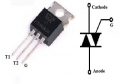
I would have expected to see three pads for the triac. I can see only two.
Usually, T2 is next to G.
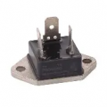
I never saw the inside of the finished product but I am quite certain that the triacs were not PCB mount types. I highly suspect that they were the big square ones that are the same footprint as a TO-3 device (they were in all likelyhood the power switch from a Peavey CS-800 power amplifier)
So they would be mounted in the chassis and then wired to this board. Does this theory work for you? You would only need two wires back here, right?
Sent from my iPhone
 

MrChips

Joined Oct 2, 2009
35,131
TO-3 package is a possibility. Isolated devices are available. What is this board designed to power?
Why 10 power outputs as per LM3914, bar/dot display?


1789258723079.png
 

Thread Starter

Failer

Joined Jul 11, 2009
27
TO-3 package is a possibility. Isolated devices are available. What is this board designed to power?
Why 10 power outputs as per LM3914, bar/dot display?
It's a power sequencer, figure 10-15 amps per output. That's why the bigger sized triacs. The picture you showed was exactly the kind I remember. In fact, I believe there's still dozens of those in his parts supplies.

As to the number of outputs, not sure what you're asking there. This board design was only used for the construction of a single finished device that was sold to a local nightclub, so original model IIRC had only 6 outputs because that's how many outputs were needed. But if I were designing this board, I too would have used all the outputs that the chip had to offer, why wouldn't you? If you don't need the extra stages, just don't populate the extra stages, right?
 

atferrari

Joined Jan 6, 2004
5,028
Not meaning to derail the topic at all, but if you happen to explore old past issues of Elektor, I recall a few sequencers worth looking at. One specific design that I posted here on AAC a while back — and was severely reprimanded for sharing — originated from that very magazine.
 

MrChips

Joined Oct 2, 2009
35,131
Looking at the LM3914 data sheet and the PCB layout, pin-3 is connected to pin-9. This means that the LM3914 is in bar mode. Outputs 1 to 10 will be activated increasingly based on the analog input on pin-5 which is 33% of the rectified AC input.

The triacs are enabling increasing amounts of current in steps of 10 A.

I do not know where the AC input single originates and what kind of equipment is used in a nightclub that needs power that increases in steps of 10 A.
 

Thread Starter

Failer

Joined Jul 11, 2009
27
Not meaning to derail the topic at all, but if you happen to explore old past issues of Elektor, I recall a few sequencers worth looking at. One specific design that I posted here on AAC a while back — and was severely reprimanded for sharing — originated from that very magazine.
Thanks I will look into this. TBH, the only reason I'm doing this is because the boards are already made. I'm going to build one, IDK, I guess it's like a tribute to my father or something? Well, anyway, like I said.. a learning experience. To be be fair, I don't really need a sequencer, already have one (see my other thread on the UJT-based one)


Although... I guess if I build another one, that gives me an excuse to buy more stereo components to put it to use...
 
Top