Please help me reverse engineer this PCB.

Thread Starter

Failer

Joined Jul 11, 2009
27
Looking at the LM3914 data sheet and the PCB layout, pin-3 is connected to pin-9. This means that the LM3914 is in bar mode. Outputs 1 to 10 will be activated increasingly based on the analog input on pin-5 which is 33% of the rectified AC input.

The triacs are enabling increasing amounts of current in steps of 10 A.

I do not know where the AC input single originates and what kind of equipment is used in a nightclub that needs power that increases in steps of 10 A.
The idea behind staging them has nothing to do with power draw, it's because audio equipment shouldn't be turned on in the wrong order, that's a good way to blow out the drivers.
The original unit was to power up a series of 800 watt power amplifiers. Think of 1975-vintage designs with massive transformers and filter caps. Not only do they pull a considerable amount of power in full operation, but the inrush to charge up 2X 30,000uF power supply filter caps is substantial.

I get that there's quite a few things about this design and application that are not in line with more modern ideas about power supplies and so-on, but think of this project as a vintage-type restoration. I'd like to build this device with the type of devices that it was originally designed for. Since it was designed 45 years ago, I guess this equipment could be considered "vintage" by that definition.
 
Last edited:

MrChips

Joined Oct 2, 2009
35,138
I am more curious about the application rather than its age.
Ok, I get it. You want to power up several separate 1000 W devices in stages, not all at once.
What device is used to turn on the sequence?
 

Thread Starter

Failer

Joined Jul 11, 2009
27
The power switch on this device.
Furman is a common brand for this type of device commonly used in A/V systems. It's not like these devices weren't available back in the day. It's just that my father was a tinkerer, builder, and small business owner. Given the choice between buying something and designing and building it himself, he was probably going to try and make it. I have an entire filing cabinet full of schematics, notes, photograph artwork for PCBs, and finished boards. There are many, many projects, analog filters of every type, Q multipliers, summing amplifiers, line drivers, compressor/limiters, and plenty of other stuff that I'm not even sure what they are.

Here is a online sale I found on a piece of equipment that was built by my father right on our dining room table when I would have been about 5 or 6 years old.

https://reverb.com/item/54994117-vintage-crosswind-sound-systems-crossover-handmade

Note the company name is the same as the board on this thread. He died 10 years ago and I have no idea how this piece of equipment ended up online. It's very possible that he built it and sold it to a musician or another local company.
 
Last edited:

AnalogKid

Joined Aug 1, 2013
12,265
Not meaning to derail the topic at all, but if you happen to explore old past issues of Elektor, I recall a few sequencers worth looking at. One specific design that I posted here on AAC a while back — and was severely reprimanded for sharing
If you can't post it again, please post the issue year and month.

ak
 

AnalogKid

Joined Aug 1, 2013
12,265
The triacs are enabling increasing amounts of current in steps of 10 A.
Nope. The TRIACs are sequentially turning on individual AC loads. The loads are audio power amplifiers with large inrush currents.

I did a similar project for an ambulance company, to stage the turn-ons of banks of lights, sirens, radios, etc.

ak
 

AnalogKid

Joined Aug 1, 2013
12,265
Following his other naming conventions, would 1 10uF cap being charged through a 1MΩ and 2MΩ resistor be about the right ramp time?
Yes. The ramp time is related to the R-C time constant. In your circuit the R is the Thevenin equivalent of the two resistors, 667K, and the C is one (or two?) 10 uF. With one cap that works out to around 6.7 seconds for the full 10-step ramp. The 3914 datasheet has all the math you need to reverse-engineer his ramp input for a more accurate guess. I would add add the second 10 uF cap to slow the ramp to greater than 1 second per stage. -ish.

Note that this is not a linear ramp, so the turn-on delays will get shorter and shorter as the stages progress. This can be approximately compensated for by designing the ramp such that only the lower voltage part of it, where it is more linear, controls the outputs. Or, he designed the ramp such that the last delay was long enough, and the delays before that were longer.

ak
 
Last edited:

MrChips

Joined Oct 2, 2009
35,138
Ian nailed it early on.

On power on, the LM3914 sees a 20-second ramp (or whatever) that activates up to 10 AC loads in sequence.

I was just curious as to where a night club would use that. I get it. It makes sense now.
 

Thread Starter

Failer

Joined Jul 11, 2009
27
Look for 6-pin DIP devices with markings that begin with "4N", or (hopefully) "MOC".
ak
Indeed they are, thanks for getting me started. Got some time to dig through all the spare parts and I have some components. The triacs are Q2045 25-amp, TO-3. The optocouplers used I believe were MO3010s. There are a bunch of MO3030s as well, but I think the 3010s were used for this. I guess I can use either depending on what y'all think, I haven't gotten to looking up their specs yet. Found several LM3914s too, so I think I have enough parts to populate the board for testing. With the LEDs right there at the optos, I can work out any kinks in the timing before I move on to playing with the high voltage side.
I'll try to get around to that, still need to dig out the Dremel drill press for the PCB, not sure where it is at the moment.
 

Thread Starter

Failer

Joined Jul 11, 2009
27
First question...
is .01uF 275VAC X-type capacitor appropriate for the triac output snubber?

I'm almost positive that normal caps were used originally. If the X-type ends up being a little too big for the current layout, I think I can swap the positions of the cap & resistor by standing the resistor up, and using it's larger spacing to mount the cap instead.


Second question...
The 3914 datasheet has all the math you need to reverse-engineer his ramp input for a more accurate guess. I would add add the second 10 uF cap to slow the ramp to greater than 1 second per stage. -ish.
I'm going to need someone to hold my hand through that part. The input pin simply says "high impedance" Do you just disregard it as a resistance and calculate the R-C alone? I'm unclear on why the 1M resistor is in parallel with the caps. Is that just to bleed it back down when it's off? Or does it limit the current to pin 5, with a total of 3M when the cap is fully charged?
 
Last edited:

ericgibbs

Joined Jan 29, 2010
21,567
Hi F,
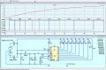
This LTspice simulation shows the LM3914 operation, switching the 10 LEDs On in sequence, over a 10 Sec period.
The Opto's in your actual circuit are represented by the switching On of the LED's in this simulation.

The values of R1 and R2 set the ramp Up time reference voltage.

When the 60Hz,10Vpk input is disconnected the R4 resistor will discharge C1 capacitor.

E
EG 2219.jpg
 

AnalogKid

Joined Aug 1, 2013
12,265
I'm unclear on why the 1M resistor is in parallel with the caps. Is that just to bleed it back down when it's off? Or does it limit the current to pin 5, with a total of 3M when the cap is fully charged?
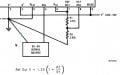
Yes, one of the functions of the 1 M resistor is to discharge the ramp capacitor(s). Also, with the 2 M resistor it forms a 1:3 attenuator. The main purpose of this is to attenuate the peak signal voltage. It also limits the input current, but the 3914 already has input current protection.

The 3914 datasheet has almost zero information about the Signal input. It does say the typical input bias current is 25 nA. The equivalent resistance of the two-resistor divider is 667K, so that works out to 17 mV. This appears as an offset error voltage at the input buffer output that drives the internal comparators.

ak
 
Last edited:

AnalogKid

Joined Aug 1, 2013
12,265
Now that Eric has given us a clean schematic (****) . . .

Note that with all 10 outputs populated, the ripple on the 100 uF filter cap will increase from almost 0 V to about 2.5 Vpp as the number of outputs increases. This could produce a small modulation in the sequential timing delays, although the VS input filter probably handles this.

And, this might cause VS to drop below the value necessary to keep L10 in the ON state. Since this circuit is known to work, this probably is not an issue. Still, I wonder what VL looks like.

ak
 

Thread Starter

Failer

Joined Jul 11, 2009
27
Hi F,
This LTspice simulation shows the LM3914 operation, switching the 10 LEDs On in sequence, over a 10 Sec period.
The Opto's in your actual circuit are represented by the switching On of the LED's in this simulation.

The values of R1 and R2 set the ramp Up time reference voltage.

When the 60Hz,10Vpk input is disconnected the R4 resistor will discharge C1 capacitor.
Holey Moley! Thanks! I'll try the board with these values and see how it works out.

You beat me to it with a whole functional circuit, but I was going to ask next about the reference resistors, what determines their value? I didn't understand the notes about adjusting the reference voltage. Is that selected to keep it stable when all the outputs are active, like it's dependent on the total current draw?

There's a (possibly apocryphal) story about Thomas Edison* and one of his inventions, he announces to his group of engineers standing around their latest project. "Lets start her up and see why she doesn't work!"

* John Fritz, Chief Engineer of Bethlehem Iron Company.
 
Last edited:

Thread Starter

Failer

Joined Jul 11, 2009
27
*smacks forehead*

Oh, right... reference. The resistors are a voltage divider to set the point of comparison for the input signal, right? And you'd do the same with ref_lo and ref_hi if you needed to move the ends of the scale around instead of just putting them at ground and V+?:cool:
 
Last edited:

Thread Starter

Failer

Joined Jul 11, 2009
27
Dug out the Dremel press and thought about how I hadn't drilled a PCB since I was a teenager, making my own with the Radio Shack kit and etching them in the garage. And I forgot how tedious it can be. Got that all done, then started to set some of the components. Only got as far as the IC socket when my soldering iron decided to stop working. It's old, like everything else, guess its time for a new one. I had been trying to use all the components I had around and not spend any real money on this project, but that's kinda an essential. New one is on the way.

In the meantime, any thoughts on the use of either the MOC3010 or 3030? It seemed to me that that the only significant difference was that the 30s are a zero-crossing model, which I assume isn't necessary when switching a triac. True or not?

Earlier, I said that I suspected that the original unit used the 3010s, and the reason that I had guessed that was that I found two packages, each containing 10 OCs. The 3030 package was still unopened, and the 3010s had 6 missing, I assumed for this project, but that's simply conjecture on my part. Is there any other important differences, and if so, which would be most appropriate for this application?
 
Top