Help finding a way to power/control this motor please!

Thread Starter

LikeTheSandwich

Joined Feb 22, 2021
209
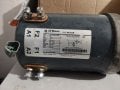
I have this motor. Should be a 72 volt, shunt DC motor as I understand it. However I have never heard of this type of motor until I received this one and did some googling on it. When googling for a shunt motor driver, I can't seem to find anything. This was taken out of a GEM golf cart originally. But a replacement controller for said vehicle is well into three figures, sometimes $1,000 or more. So I'm trying to find a cheaper option. I don't need it to be super efficient, but I would like it to be fairly powerful as I'm going to build a vehicle from scratch for it. Probably just some kind of little side by side, so even though it's full input rating is 5 KW, I don't think I'll ever be putting it close to that except in acceleration sometimes. Is it possible that I can just current limit the field winding and run that at a good voltage basically creating electromagnet, then simply treat the armature windings as a brushed DC motor? Or will that ruin something? I did something similar with an alternator that I converted and used on a previous go-kart by simply providing 12 volts to the armature winding and then treating it as a brushless DC motor and getting a brushless controller. It had a hard time starting at zero RPM sometimes but as soon as it got going it worked fine. Would that also work for something like this? Or does anyone know of a relatively inexpensive 72v shunt motor controller? Thanks!

EDIT: Also does anybody know what that three wire connector thing is for on the back of it?
 

Attachments

MaxHeadRoom

Joined Jul 18, 2013
30,795
Most DC shunt motors are PM field now, not wound.
The nice thing about it you have more control, i.e., in this case use one of the Treadmill controllers and adapt for using this motor, DC field could be fed from one of the incline circuits.
One of the MC2100's could easily be adapted.
The 3 wires are most likely a tach, see where they terminate to.
 

Thread Starter

LikeTheSandwich

Joined Feb 22, 2021
209
Most DC shunt motors are PM field now, not wound.
The nice thing about it you have more control, i.e., in this case use one of the Treadmill controllers and adapt for using this motor, DC field could be fed from one of the incline circuits.
One of the MC2100's could easily be adapted.
The 3 wires are most likely a tach, see where they terminate to.
Thanks for the reply. I was looking at that from amazon, looks like it's less than $200, it's listed as a 110 volt model though. Would it work from 72 volts DC? Also how are you suggesting I power it from an incline circuit? I'm not sure I understand. Also what do you mean by PM field not wound? You mean permanent magnet instead of having an actual field winding? This motor is very old, I think they stopped manufacturing it like 15 years ago or more. I'm not sure if it was clear in the picture, but there's both Field and armature connections. F1/F2 and A1/A2. But am I right that if I just apply an appropriate current to the field winding, it would then kind of work like a permanent magnet brushed motor? And then I could just worry about applying a brushed motor controller to the A1 and A2 connections? Also that controller looks like it would be woefully underpowered, it really doesn't look like it can handle the 60+ for this motor.

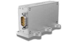
Something like this perhaps from Amazon:
I think it would work with a fixed field current for your motor.
Am I understanding what you're saying correctly? That what I said earlier, if I excite the winding, then it would function kind of like a brushed DC motor? If so, that controller says brushless, so I'm not sure if it would work necessarily? But I'm sure I could find a brushed controller or something, I just wanted to verify if it would function similar to a permanent magnet brushed motor if I was to excite the field winding. So just to verify, are you agreeing with that assessment?
 
Last edited:

B-JoJo-S

Joined Jan 3, 2026
503
what do you mean by PM field not wound?
Permanent Magnet, not field windings. Field windings create a magnetic field, same as a permanent magnet. What Max said about it being more controllable is that with a field wound motor you can control the amount of force of a magnetic field, whereas a permanent magnet has its field present at all times and can not be changed. Can not be reversed. With a field wound motor you can change the polarity if the field simply by reversing the current through the field windings, and thus - you have a reversible motor. But you still have a reversible motor simply by changing the polarity of the armature windings. Such a motor (wound, not PM) can be run from AC or DC - if I have that right. If not - someone will point out my error. A permanent magnet motor can not be run from AC, not without rectifying the current to DC.
 

crutschow

Joined Mar 14, 2008
38,762
Am I understanding what you're saying correctly? That what I said earlier, if I excite the winding, then it would function kind of like a brushed DC motor? If so, that controller says brushless, so I'm not sure if it would work necessarily? But I'm sure I could find a brushed controller or something, I just wanted to verify if it would function similar to a permanent magnet brushed motor if I was to excite the field winding. So just to verify, are you agreeing with that assessment?
Yes that is my assessment, but I've had no direct experience doing that.

Perhaps Max, or someone else with more experience, can chime in on that.
 

MaxHeadRoom

Joined Jul 18, 2013
30,795
Something like this perhaps from Amazon:
I think it would work with a fixed field current for your motor.
This is aimed at a BLDC type motor, you may find a DC brushed version,, but you need a separate field supply, Also in some applications you need field loss protection, to avoid a tun-away condition., if the field happens to fail.
Again, it depends on the application.
'
 

BobTPH

Joined Jun 5, 2013
11,638
Something it says in the motor faceplate is bothering me:

F1 and A2 must be the same polarity.
For CW rotation, reverse the field or armature connections.

How can you reverse one connection while keeping F1 and A2 the same polarity? This seems contradictory to me.
 
Two points about shunt wound motors. 1/ The do not work on AC. I think the reason for this is the the field winding has a significant inductance so the the phase of the current will be out of phase ith the voltage. The armature has quite low inductance so that the armature current will be about in phase with the voltage. In the case of series motors the armature and field currents must be in phase as they are in series. 2/ Reducing the field current on a shunt motor increases it's speed and reduces the torque.
Les.
 
Last edited:
Not all BLDC motors have internal electronics, often just the three commutation detection devices, for e.g. the servo motors I use have the commutation track included on the rear fitted encoder.
When replacing an encoder, the track has to be positioned at exactly the right point.
Done with a scope and back-feeding (rotating) the motor.
 
I have this motor. Should be a 72 volt, shunt DC motor as I understand it. However I have never heard of this type of motor until I received this one and did some googling on it. When googling for a shunt motor driver, I can't seem to find anything. T
This type of motor has been around for eons, it supercedes the PM rare -earth magnet fields now mainly fitted
 
It simply states, for CCW rotation, A1 and F2 to be the same polarity.
Swap either the field, or the armature polarity and the motor will rotate CW.

The 3 wire connector is probably a speed feedback device.

A brushless motor controller (BLDC) will not work with that motor.

The field winding is normally connected to the battery via a relay when motion is called for,
since it pulls 5.7A to generate the magnetic field that would otherwise be provided by permanent magnets.

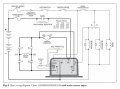
The armature circuit controller will be a PWM type. EG:-

https://www.noco-evco.com/product/1205M-6B403.htm

Look at the manual referenced on that web page. It gives circuit diagrams for exactly what you're looking for.
One option.
DCmotor controller.JPG
 
Top