But this isn't a full bridge, it's a half-bridge with two transistors in parallel.
Provided that the top pair is on when the bottom pair is off, and there is sufficient dead-time to allow the IGBTs to turn off, it will work.
But this isn't a full bridge, it's a half-bridge with two transistors in parallel.
Provided that the top pair is on when the bottom pair is off, and there is sufficient dead-time to allow the IGBTs to turn off, it will work.
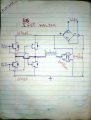
Top MOSFETs and bottom MOSFETs must never be on at the same time.
There must be a short time when no MOSFETs are on.
Bottom MOSFETs are driven by a driver sitting on (-).
Top MOSFETs is driven by a signal that is not related to (-) but by (AC)
Top MOSFETs and bottom MOSFETs must never be on at the same time.
There must be a short time when no MOSFETs are on.
Bottom MOSFETs are driven by a driver sitting on (-).
Top MOSFETs is driven by a signal that is not related to (-) but by (AC) View attachment 221162
Top MOSFETs and bottom MOSFETs must never be on at the same time.
There must be a short time when no MOSFETs are on.
Bottom MOSFETs are driven by a driver sitting on (-).
Top MOSFETs is driven by a signal that is not related to (-) but by (AC) View attachment 221162
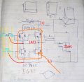
That arrangement (post #1) with the coil connected by a capacitor is a common way of doing things. The coil will see ±half the supply voltage and that may be what the design expects.
Whichever of the inputs is active there will be one top transistor and one bottom transistor turned on. This puts them conducting across the supply - a near short circuit.
No, this circuit (post #8) will destroy the transistors.
Whichever of the inputs is active there will be one top transistor and one bottom transistor turned on. This puts them conducting across the supply - a near short circuit.
That arrangement (post #1) with the coil connected by a capacitor is a common way of doing things. The coil will see ±half the supply voltage and that may be what the design expects.
 Facebook
 Google
 GitHub
 Linkedin