Facebook
 Google
 GitHub
 Linkedin
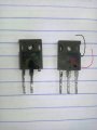
just changed the transistors now with 60n60 1:1, but unfortunately it blown offNO, you will blow the transistors as they will turn on together and short out the supply.
You need to cross connect the Bases so that opposite transistors conduct, So top Left and Bottom Right bases , top Right and bottom Left.
What could be the problem?
just changed the transistors now with 60n60 1:1, but unfortunately it blown offThanks
What could be the problem?
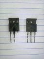
just changed the transistors now with 60n60 1:1, but unfortunately it blown offTop MOSFETs and bottom MOSFETs must never be on at the same time.
There must be a short time when no MOSFETs are on.
Bottom MOSFETs are driven by a driver sitting on (-).
Top MOSFETs is driven by a signal that is not related to (-) but by (AC)
View attachment 221162
What could be the problem?
.jpg")
.jpg")
.jpg")
.jpg")