Piezo Transducer Driver Circuit

Thread Starter

h.yakub

Joined Mar 11, 2019
97
hi,
I will at the simulation,
Why have you have changed the TX circuit back to the original design.? also you have two transducers across the pz to 0v output.
Both of the transducers are not a correct representation of a real transducer.
E
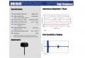
Yes, I have changed back to the original one because, I will not be able to use Transformer, so I had to go with arrangement of this circuit, I guess there is only one network (3 ohms, 3600pF) that act as the piezo element, the other is the simulated echo signal from your previous design....
Ohk, I see the confusion, the network containing 10uH and 1 ohm resistor is the resonator circuit part...it is not the transducer part
 
Last edited:

Thread Starter

h.yakub

Joined Mar 11, 2019
97
hi,
Got the basic data from the piezo d/s you posted and worked with LTS to get an indication of the inductance.
Try this asc sim.
E
Okay,
Well what do you think about the TX1MHz.asc file with the inductor and all? Is it feasible to work with?
But, the voltage it generates is about 25 Vp-p which is not sufficient to get echo from the container....How can increase this Vpp voltage with the current circuit components?
 

ericgibbs

Joined Jan 29, 2010
18,849
hi,
You need to put more energy into the piezo in order to get a detectable echo back from the water/air interface, then back through the metal container.
This means a transformer or a much higher drive voltage source is required.
The downside is the ringing of the transducer, which the amplifier has to suppress, also a swept time controlled gain amplifier is advisable.

The design of the LTSpice simulated piezo is not an issue, providing it resonates around 1MHz.

E
 

Thread Starter

h.yakub

Joined Mar 11, 2019
97
hi,
You need to put more energy into the piezo in order to get a detectable echo back from the water/air interface, then back through the metal container.
This means a transformer or a much higher drive voltage source is required.
The downside is the ringing of the transducer, which the amplifier has to suppress, also a swept time controlled gain amplifier is advisable.

The design of the LTSpice simulated piezo is not an issue, providing it resonates around 1MHz.

E
Yes, exactly you're right, but how can I increase the drive voltage? It seems that if I change values of components the circuit is somehow limited to generate only upto 30V maximum....
 

ericgibbs

Joined Jan 29, 2010
18,849
Yes, exactly you're right, but how can I increase the drive voltage? It seems that if I change values of components the circuit is somehow limited to generate only upto 30V maximum....
hi,
You will see in my post #49, it is a step up transformer that drives the piezo.
E
 

Thread Starter

h.yakub

Joined Mar 11, 2019
97
hi,
You will see in my post #49, it is a step up transformer that drives the piezo.
E
Yes, I know you suggested to go with step up transformer, but right now I cannot wind up a transformer at my disposal, that is why I am moving with the original circuit.
can you suggest some changes in the original circuit that would boost the drive voltage to 60-80 volts ....?
 

ericgibbs

Joined Jan 29, 2010
18,849
On the post #91 circuit, you have changed the parameters of the first piezo.??
You also still have a second piezo connected.?
Have you confirmed with the piezo supplier what is the maximum power rating.??

We seem to be going around in ever decreasing circles.:rolleyes:

I would suggest you reappraise the viability of the project.

E
 

Thread Starter

h.yakub

Joined Mar 11, 2019
97
On the post #91 circuit, you have changed the parameters of the first piezo.??
You also still have a second piezo connected.?
Have you confirmed with the piezo supplier what is the maximum power rating.??

We seem to be going around in ever decreasing circles.:rolleyes:

I would suggest you reappraise the viability of the project.

E
Yes, I am attaching a datasheet of piezo that I have at my disposal (DM-1000), This piezo has a maximum voltage reading of 100 Vp-p. This piezo is the one I am using for testing purposes...
 

Attachments

Danko

Joined Nov 22, 2017
1,835
Also, I guess the circuit that we designed is simulating well, but the only thing is the transducer could get an echo back from the container. Any idea is to what else can we do so that we could get echo back from inside the steel container.
In metal container original transducer pulse with high efficiency transforms
to long lasting walls oscillations (like in bell).
Therefore prospective echo pulse simple not exists.
It is why they use this method:
upload_2019-3-15_16-52-20.png
 
Last edited:

Thread Starter

h.yakub

Joined Mar 11, 2019
97
In metal container original transducer pulse with high efficiency transforms
to long lasting walls oscillations (like in bell).
Therefore prospective echo pulse simple not exists.
It is why they use this method:
View attachment 172390
Hi Danko,
Thanks for your input on this topic, really appreciate it.
This is turning out to be some kind of challenging task for me as well, but I do believe that ultrasounds (the one that works in fluid medium) can be the key to finding fluid levels inside sealed metal containers. I just need to find a right spot or enough power to be able to do so....(y)
 

Danko

Joined Nov 22, 2017
1,835
This is turning out to be some kind of challenging task for me as well, but I do believe that ultrasounds (the one that works in fluid medium) can be the key to finding fluid levels inside sealed metal containers. I just need to find a right spot or enough power to be able to do so....(y)
Your problem can be solved by back signal FFT processing.
Spectrum of this signal definitely depends on fluid level inside container.
 

Danko

Joined Nov 22, 2017
1,835
Okay, now we are getting somewhere, but how do I produce knock and detect the changes in frequencies..
Knock is produced by transducer (alone pulse).
Signal after knock, received by transducer,
processed by program (Fast Fourier Transform, FFT).
Hence you can draw conclusion about fluid level.
 
Top