Facebook
 Google
 GitHub
 Linkedin
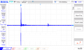
Its only a LTS simulation, the signal you get from the real circuit will be different.Hi Eric,
Why don't we use sine wave as simulated echo signal, rather than using a pulse signal, because the nature of the echo that I am seeing is very close to sine wave signal rather than a pulse signal..?
Post a signal image from the scope screen.

")