Piezo Transducer Driver Circuit

Thread Starter

h.yakub

Joined Mar 11, 2019
97
Hi ericgibbs,
I am using an arduino to generate the 1 MHz burst pulses, with a preset duty cycle of 50% (as I cannot afford to buy a Function generator :p), I cannot change the duty cycle from 50%.
I am using the original circuit right now, and the circuit you have posted, it includes, a 12uH inductance with 2200pF capacitor and a parallel 1 K resistor, is it a model of Transducer ?!
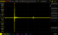
Also see the attachment of echo, I am receiving on plastic bottle, at full level of liquid around (22 cm). This is a pretty strong echo.
Also, do I need to resonate the transducer?
 

Attachments

ericgibbs

Joined Jan 29, 2010
18,849
hi,
Consider what is happening in the piezo when the 1MHz drive pulse is not at resonance with the natural frequency of the piezo, the compression and expansion effect of the piezo crystal is not is sync with the drive signal, so you get a damping signal, look at your TX image its not clean.
Build a simple 555 Astable at 1MHz and try sweeping either side of 1MHz when driving the 2N7000.
E
AA1 12-Mar-19 10.56.gif
 

Thread Starter

h.yakub

Joined Mar 11, 2019
97
hi,
Consider what is happening in the piezo when the 1MHz drive pulse is not at resonance with the natural frequency of the piezo, the compression and expansion effect of the piezo crystal is not is sync with the drive signal, so you get a damping signal, look at your TX image its not clean.
Build a simple 555 Astable at 1MHz and try sweeping either side of 1MHz when driving the 2N7000.
E
View attachment 172123
Hi Ericgibbs,
I have also used a different 1 MHz piezo transducer, the scope images of it is as below, I guess this one's is resonating, Please check. I have used 2 MHz frequency at 50% duty cycle from arduino.
 

Attachments

Thread Starter

h.yakub

Joined Mar 11, 2019
97
Hi EricGibbs,

Can you also share any circuit for 555 timer astable circuit to generate the frequency with adjustable frequency and duty cycle.
hi,
That second image looks much better, what does the glass and container echo show.?
E
There is no echo seen on steel container...I am trying to figure out why this is happening, the transducer gives good results on plastic, glass, but when I try it on steel, it does not show any echo.
I have tried giving more power, but no result..
Also, I used a piezo with big diameter (50 mm) to increase echo sensitivity but still got no results...
I am out of options now....please suggest any solution...
 

ericgibbs

Joined Jan 29, 2010
18,849
hi,
This is one option for the 7555 Astable.
One 755 is1MHz and the other for Gating 10 pulses.
E

EDIT:
You could use the MCU to generate the Gate pulse , instead of the right side 7555
 

Attachments

Last edited:

Thread Starter

h.yakub

Joined Mar 11, 2019
97
hi,
This is one option for the 7555 Astable.
One 755 is1MHz and the other for Gating 10 pulses.
E
This I am able to do with Arduino right now, I am getting the same output from arduino (10 pulses).
What changes can I do to driver circuit of piezo to get maximum output?
I am using a XL6009 Boost converter to step up the voltage from 5 V to 50 V, so I am giving 50 V at drain of 2n7000.
 

Tonyr1084

Joined Sep 24, 2015
7,899
Ultrasonic sound waves bounce off the first and last surfaces. If there's an imperfection inside the wall of the steel container you will see another reflection. Depending on how big the imperfection is - that will show in the size of the return signal. If directly behind the last surface there is a fluid then the sound wave should travel further through the fluid until it reaches the far side of the container (the inside). Then there should be another echo from the first surface of the container (inside) then finally the last surface. It's possible you're seeing a reflection but your instrumentation is looking for a signal to come back sooner than the second echo, the last surface of the steel container. I know this because I was trained in UT NDE (Ultrasonic Transducer Non Destructive Examination) for steel tanks. Particularly in detecting the location of imperfections within the welds. Some of the tanks had walls 3 1/2 inch thick. The welder had to gouge out the weld and clean out the imperfection. It was critical to know exactly where and how deep the imperfection was. That all had to do with timing of the reflections and how strong they were. The imperfections were found via X-Ray NDE. But because the location of the film corresponding to a particular seam and distance from a given datum was somewhat speculative (not exact) it was necessary to identify the exact location so the welder didn't have to cut out a foot of weld just to find the inclusion.

Try slowing down the sweep of your scope and you might find the reflection you're looking for.
 

Thread Starter

h.yakub

Joined Mar 11, 2019
97
Ultrasonic sound waves bounce off the first and last surfaces. If there's an imperfection inside the wall of the steel container you will see another reflection. Depending on how big the imperfection is - that will show in the size of the return signal. If directly behind the last surface there is a fluid then the sound wave should travel further through the fluid until it reaches the far side of the container (the inside). Then there should be another echo from the first surface of the container (inside) then finally the last surface. It's possible you're seeing a reflection but your instrumentation is looking for a signal to come back sooner than the second echo, the last surface of the steel container. I know this because I was trained in UT NDE (Ultrasonic Transducer Non Destructive Examination) for steel tanks. Particularly in detecting the location of imperfections within the welds. Some of the tanks had walls 3 1/2 inch thick. The welder had to gouge out the weld and clean out the imperfection. It was critical to know exactly where and how deep the imperfection was. That all had to do with timing of the reflections and how strong they were. The imperfections were found via X-Ray NDE. But because the location of the film corresponding to a particular seam and distance from a given datum was somewhat speculative (not exact) it was necessary to identify the exact location so the welder didn't have to cut out a foot of weld just to find the inclusion.

Try slowing down the sweep of your scope and you might find the reflection you're looking for.
Hi Tonyr,
Thanks for your reply.
I am trying to measure the fluid inside the steel container, as you said that the first echo is reflected from inner surface of the wall and second from the surface of fluid, but i am not able to see first or second echo too, I also reduced my sweep upto the point..but still nothing. Are you suggesting that there might be some imperfection in the container that restricts the echo from coming back or so?
 

ericgibbs

Joined Jan 29, 2010
18,849
hi,
I would say the circular shape of the metal wall at the other side of the container will not give a direct echo, it will be dispersed due to the curved reflecting surface shape.
Have you considered a second piezo detector/receiver at the other side of the container, that is in line with the transmitted beam.?
E
 

Thread Starter

h.yakub

Joined Mar 11, 2019
97
hi,
I would say the circular shape of the metal wall at the other side of the container will not give a direct echo, it will be dispersed due to the curved reflecting surface shape.
Have you considered a second piezo detector/receiver at the other side of the container, that is in line with the transmitted beam.?
E
Yes, I have tried placing another transducer in line with the transmitted beam, still I am not receiving any Echo. I have filled these containers with water as test fluid. The Theory is that the ultrasound will reflect back from the surface of the water and produce an Echo. Currently I am placing the Ultrasonic Transducer at the bottom of the containers. I have also tried placing them at Top and Side wall of the container still get no results.

I am using a Transformer now, for driving the circuit, I will share the scope Images with you soon today....
 

Thread Starter

h.yakub

Joined Mar 11, 2019
97
Hi,

I have designed another drive circuit with Transformer. Please Find the circuit schematic & scope results.
In a nut shell:
1. The transformer resonates the piezo quite well, but there is a huge time interval for ring (~500 us) which is not quite good for low measurements.
2. I see some eye liked shape in response when I place it at the bottom of the container, not sure which one is the echo or is to be considered as echo.

If this circuit is quite good, then please suggest improvements to reduce ringing of the piezo.

Thanks.
 

Attachments

ericgibbs

Joined Jan 29, 2010
18,849
hi,
Have you tried reducing TX pulse from 10 cycles to 5 cycles of 1MHz.?
How do you plan to read the echo signal on the final design.?

Ringing is always a problem, usually the receiver has an adjustable Suppression period gate.
and also Time Controlled Gain on the receiver amplifier.

E

EDIT:

Looking at the ringing image, it decays in approx 20uSec.
If the container diameter is say 0,5mtr and velocity of sound in water is 1500mtr/sec, the echo delay will be 0.5mtr/1500mtr approx 330uSec [ times by 2 for a reflected path] 660uS.
So the ringing should not be a problem.

Are you trying to determine if the water level in the container is above or below the ultrasonic beam.????
 
Last edited:

Thread Starter

h.yakub

Joined Mar 11, 2019
97
hi,
Have you tried reducing TX pulse from 10 cycles to 5 cycles of 1MHz.?
How do you plan to read the echo signal on the final design.?

Ringing is always a problem, usually the receiver has an adjustable Suppression period gate.
and also Time Controlled Gain on the receiver amplifier.

E
Yes, I tried reducing the number of pulses from 10 pulses all the way down to 2 pulses, but what I see is the Vpp decreases, the power decreases. At 20 pulses also, I see that the power gets decreased, at 10 pulses the output power is maximum. I don't know the reason is to why the circuit behaves like that.
To read the echo, I am planning to isolate the trigger pulse from the echo, filtering and amplifying then send back to arduino.
If you can suggest a circuit for echo detection at 1 MHz, that would be much helpful...
 

ericgibbs

Joined Jan 29, 2010
18,849
hi,
With most piezo transducers it takes a few cycles of the drive signal in order to reach resonance.

For the RX echo a common method is use a resistor connected in series with two diodes, which are connected in anti parallel.
I will post a diagram.
E
Note my edit in post #35
 

Thread Starter

h.yakub

Joined Mar 11, 2019
97
hi,
Have you tried reducing TX pulse from 10 cycles to 5 cycles of 1MHz.?
How do you plan to read the echo signal on the final design.?

Ringing is always a problem, usually the receiver has an adjustable Suppression period gate.
and also Time Controlled Gain on the receiver amplifier.

E

EDIT:

Looking at the ringing image, it decays in approx 20uSec.
If the container diameter is say 0,5mtr and velocity of sound in water is 1500mtr/sec, the echo delay will be 0.5mtr/1500mtr approx 330uSec [ times by 2 for a reflected path] 660uS.
So the ringing should not be a problem.

Are you trying to determine if the water level in the container is above or below the ultrasonic beam.????
If you observe closely, then the ringing is about 500 uSecs.
I am trying to determine the water level below the ultrasonic beam i.e, as the transducer is placed at the bottom of the container, the ultrasound travels through water and gets reflected back from the top surface of the water.
 

ericgibbs

Joined Jan 29, 2010
18,849
hi,
This is your ringing image, I thought that it was set for 1uSec/div, if its 50uSec/div of the scope, that not the piezo thats ringing, it most likely your coupling transformer.
Do you have details of the transformer to post.?
E
 
Top