PIC vs Arduino

elec_mech

Joined Nov 12, 2008
1,500
Chris,

Are you looking to update your outdoor soccer score display? Just curious.

You can just about bend any microcontroller (uC) solution to your will one way or another. To help narrow the list, I think the question to ask is what language do you want to use to program in?


Assembly, Basic, and C are the most common programming languages for uCs.
  • Assembly is low-level, has a high learning curve, requires an order of magnitude more code than any of the others, but it's free.
  • C is mid-level (many will disagree with me here), has a steep learning curve in my opinion (not near as bad as assembly), but it is the choice of most businesses if you make a career out of it and you can get demo or limited capability versions for free or darn near it. You can get the pro versions for $100 or more (been awhile since I've looked at these though).
  • Basic is high-level and very easy to get started in. Depending on the uC used, you can spend nothing to almost $300 for a pimped out pro version (for PICs).
Levels, in layman's terms, simply refer to how much code you need to put into the program.

Low level requires a lot of code because you have to go step-by-step. Example:
1) Move your right arm over the desk.
2) Move your right hand above the pen.
3) Lower your right hand.
4) Grab pen with right hand.
5) Lift right arm.

Mid-level requires less.
Example:
1) Move your arm over the desk.
2) Grab pen with right hand.
3) Lift right arm.

High-level least of all.
Example:
1) Pick up pen.

This is a very crude example, but it gives you an idea.

Personally, I like Basic. It's quick to learn and it's like riding a bike if you put it down for awhile. I've written one program in C and I'd have to relearn C before I could write something in it again because I don't use it regularly. Again note, this is simply my opinion and limited experience, others may disagree so you'll have to decide for yourself.

If you opt to go with PICs, I like PIC Basic Pro. It is a bit pricey, so maybe someone here can suggest an alternative.

Another uC option to consider is a PICAXE. These have free, full featured Basic software. The caveat is, these are interpretted Basic, meaning they are bit slow. You wouldn't want to use them to control something requiring fast timing or lots of inputs that need checking simultaneously. However, for basic clocks, scoreboards, and the like, they should be fine. All you need is the chip and a serial-to-USB converter (unless your computer has an RS-232 serial port, then you just need the IC). For clock applications, you'll want an external clock such as a DS1307 or a simple 1Hz generator. Take a look at this thread for an example.

Now, whatever you decide, be sure to look for a forum dedicated to that language/hardware to help you out. Good luck.
 

Thread Starter

chrischrischris

Joined Feb 18, 2012
317
Hey everyone, thanks tones for all the advice you've given me to chew on. I really need to read all the responses in more detail to "absorb it" - it's midnight here in Oz. I'll then get a bit more detailed in my questions. As much as I can't wait to delve into programming, I should start off simple and then progress to advance to more complex systems/code. At a "glance" it seems Arduino may be the "easiest" to start with, but I need to do my homework now and investigate all the suggestions / advice above.

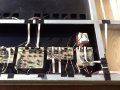
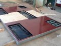
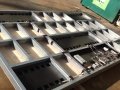
Mech_elec, yes hi again and yes you guessed correctly. I've finished my scoreboard and installed it last week. I'm going to upload it soon as a completed project. I'm currently just tweeking a power issue and count-down pause anomaly - it was working perfectly before I installed it!!! It really has me now wanting to rebuild my 5 boards with 1 board that is based on programming rather than relying on discrete components - 4511s, 4017s, etc. Time to "step-up" - but it was a great learning curve. Below are some pics on the electronics and the 3/4 finished board...
01.JPG 04.JPG 02.JPG 03.JPG
 

elec_mech

Joined Nov 12, 2008
1,500
That is looking sweet!

Whatever you decide on, be sure it can communicate easily via I2C and/or SPI. This should be listed somewhere with the IC specifications, probably in the datasheet. The reason for this is you'll need driver chips with lots of pins to control the 7-segments. You can do with this with I/O expander ICs such as the MCP23017 (currently using this on a PICAXE project) or something like a MAX7219/7221. The MAX ICs accept I2C or SPI, respectively, and each chip controls up to eight 7-segment digits - makes coding and timing MUCH easier. For that convenience, you pay about $10USD per chip, but not a bad tradeoff for everything you want to do.

That said, before you make a decision, do some research to verify the uC you select will work with a MAX7219/7221 and see if there are some examples - this will make your life a lot easier.

I can't promise to be much help with the uC you select, but I can help you with the hardware design if you'd like (selecting driver ICs, etc.) - just let me know.
 

pujulde

Joined Jul 24, 2013
111
What is arduino? Arduino is AVR microcontroller with bootloader, you can just write simple programs and it will execute it. you need no work with registers separately as in case of using controllers without bootloader, arduino is like an open source language with strong libraries. You can visit tronixstuff.wordpress.com
 

tshuck

Joined Oct 18, 2012
3,534
What is arduino? Arduino is AVR microcontroller with bootloader, you can just write simple programs and it will execute it. you need no work with registers separately as in case of using controllers without bootloader, arduino is like an open source language with strong libraries. You can visit tronixstuff.wordpress.com
...ummm...no. The bootloader has nothing to do with whether or not "you need no work with registers separately", whatever that means...

The bootloader is responsible for manipulating the program memory, which, for the Arduino, means the program is given to the bootloader over a UART interface...What is getting transferred is the hex file generated from the compiler and information for the bootloader.
 
Last edited:

pujulde

Joined Jul 24, 2013
111
i mean that in case of working with MC you need to point out the address of every register, but in arduino its done by bootloader
 

Thread Starter

chrischrischris

Joined Feb 18, 2012
317
Some time back MMcLaren made the comment that he wasn't keeping up with my scoreboard project as it was "too agonising to watch" - should be done with programming. His suggestion was to do something similar to his project https://forum.allaboutcircuits.com/showthread.php?t=69548 - (a PIC 4-Digit 99 minute timer). The mention of multiplexing I wasn't keen on as my board has been built with 15 digits, each with it's own 10 core ribbon cable (8 used), however the use of a single controlling chip I absolutely agreed with (as my 2nd project). He suggested a MIC5891 pic processor (actually 4 of them). So that was my starting point.
 

elec_mech

Joined Nov 12, 2008
1,500
At a quick glance of the data sheet, the MIC5891 appears very similar to the 74HC595. These effectively add 8 more outputs to a uC which is great. However, you still have to do quite a bit of programming and perform your own multiplexing routine. I like the MAX7219/21 because it takes care of the multiplexing - you just send a command as to what each digit should show and it takes care of the rest. With either choice, you'll still need some transistors to handle the voltage and current requirements of your large displays, but your overall parts count will go down considerably and you can make changes on the fly, e.g., make the score digits blink/flash when a certain score is reached.
 

Rbeckett

Joined Sep 3, 2010
208
Chris, I apologize for not reading every reply, but to make it as simple to understand as possible consider it this way. Arduino is a simplified language to communicate what you want the chip to do. C and C++ are not simplified but for the most part will do exactly the same as arduino code, it is just a bit more esoteric and requires a bit more knowledge of the inner workings of the chip to accomplish that goal. It can be compared to working on a simple WYSIWYG word processor compared to Quark which is professional publishing software for printers and publishers. Another comparison would be Quick books for your home Business or SAP for a global corporation. They essentially do the same things but how they arrive at the end result is much more in depth and requires much more info and understanding to incorporate it completely. I would start with Arduino to learn the basics of getting a chip to do the tasks you desire right now and advance to the PIC Microcontrollers in the 16 and 18 families later on when you are ready to learn a higher level programming language like C or C++. Just my .02, but that's how I am doing it so I can fully understand what I am doing and build on my knowledge that way.

Wheelchair Bob
 
Last edited:

Thread Starter

chrischrischris

Joined Feb 18, 2012
317
Thanks again for all the advice from everyone. I've read through all the posts and gone to all suggested links. I'm feeling more confident on what's available even in programming now.

I'm feeling a bit of an infant here in these replies with words and acronymns such as PIC, MCU, AVR, uC, ASM, ARM, expanders, shift registers, bootloaders, UART interface, etc. As we'd say in Australia.. Maaaaate - what tha? So I did alot of reading/research to try see what these all were/meant.

Reading the suggestions it seems Bance, donpetru, Shagas, tshuck, MrChips, sirch2, New_voodoo, mech_elec pujulde and Rbeckett all suggest that Arduino is a good simple start, then consider going more complex later (once I learn to walk). Sorry eric007, you've sort of been outvoted. I think I'll go with the Arduino that's for "lazy people" - I know that was tongue in cheek.:)

I've googled and found a unit here in Australia - Arduino Mega 2560 for just over $20. The Uno only has 16 digital IOs (of which 6 can be PWM outputs) and 6 analogue inputs. The Mega has 54 (14) and 16 respetively.

http://www.ebay.com.au/itm/Mega-2560-R3-Arduino-Compatible-Free-USB-Cable-AU-Stock-/171076388710

What I'd like to test up front with this board is running a four small 7 segment display to:
  • Count by 1 after a manual input
  • Allow setting a time (i.e. 45:00)
  • Count backwards from that time
  • Pause, restart the count down
  • Change the countdown time
  • Create a forward advancing clock
  • Create a temperature reading via an LM35
  • Vary the 7 segment displays via PWM using an LDR and the chip as a comparitor?

I assume all the above is achievable on the Arduino? Just one other question, multiplexing. Can the 4 digits be controlled by this unit via a single length 8 core ribbon cable? If so, does something have to be added to each digit for it to know when it is it's turn to "shine"? Excuse my ignorance.
 
Last edited:

elec_mech

Joined Nov 12, 2008
1,500
For the record, I'm not in the Arduino camp. I have nothing against it, it seems quite popular, but I have no experience with it nor do I have a desire to relearn C <shudder>.

Can it do all you ask? Probably, but hopefully someone else here will know for sure. I know a true PIC or AVR could.

Going into opinion mode, I'd suggest looking at the PICAXE. It uses BASIC which is extremely easy to learn and all you need is the IC, a simple programming cable and a breadboard. That said, I know it can handle each of the tasks you mention individually, but I'm not 100% sure if it can handle them simultaneously due to its speed limitation (of course, they offer faster ones, so maybe they can). However, you can give it a shot and once you're comfortable programming, you can always "upgrade" to a true PIC and find a decent BASIC language or, having your feet wet and confidence up, look at a C language to try.


In whatever you decide to go with, here's some thoughts on approaching your project.
  • Determine how many inputs and outputs you need from the uC. This is referred to as I/Os (inputs/outputs). Every uC has a finite number of them, so you want to map out your needs before selecting one.
  • Do any of your tasks require analog-to-digital (A/D) conversion? An example is a sensor that outputs a changing voltage. The analog voltage is then changed into a hard number the uC can understand. If so, make sure the uC has A/D inputs and that you have enough. Your LM35 will require an A/D input on the uC since it outputs an analog voltage with respect to temperature.
Stepping through your desired tasks:


Count by 1 after a manual input:
  • User presses a momentary button to advance count by one?
  • Does this in turn change the display?
  • Is this for the score? Then two buttons total - one for home, one for visitor?
  • Do you need to count back or reset as well (2-4 additional buttons)?
Allow setting a time (i.e. 45:00)
  • Single momentary button to advance seconds then minutes?
  • Or separate buttons for each?
Count backwards from that time


Pause, restart the count down
  • So far, minimum of 3 buttons, possibly five so far: increase (1-2), decrease (1-2), start/pause (1).
  • Do you want to throw in a reset button to set the count to 00:00 as well?
Change the countdown time
  • How do you mean? Like pause then increase or decrease the time or something else entirely? You can do this or force the user to first hit the reset button so time can't be changed accidently.
Create a forward advancing clock
  • Not sure what you mean here. Is this a second clock (first one counts down, this one counts up)?
  • If yes, how many digits? MM:SS (4)?
  • Same number of buttons as the countdown clock (increase, decrease, start/pause)?
  • If yes, you may consider using a toggle switch so user can use same buttons to control both clocks and simply flips switch so uC knows which clock to control. This would reduce you total I/O requirement.
Create a temperature reading via an LM35
  • Be sure the uC has an A/D pin
  • Is this two digits?
Vary the 7 segment displays via PWM using an LDR and the chip as a comparator?
  • Need another A/D pin to read the LDR.
  • Controlling the digits and their brightness can be done on the uC (like MMcLaren did) or a separate dedicated chip. If you do this on the uC you'll need a lot of I/O pins, a fast uC, and you'll spend a lot of time programming. MMcLaren's project is awesome, but it only controls, what was it, 4 digits and only keeps time. You need to keep at least two times, two scores, be able respond to multiple button presses quickly, and monitor temperature and ambient light. You do not want to add multiplexing the digits and varying PWM into your code.
  • I suggest a separate chip designed to take care of this for you such as the MAX7219/21. One of these will handle multiplexing up to eight digits including PWM. All you need is to send it a command through a few I/O pins telling it what the digits should show and how bright they should be.
Can the 4 digits be controlled by this unit via a single length 8 core ribbon cable? If so, does something have to be added to each digit for it to know when it is it's turn to "shine"?
I'm not sure what you mean by controlling four digits with an 8 core ribbon cable. Ah wait, you mean can you multiplex and control 4 digits with 8 wires? Hmm, no. Assuming each digit is 7-segment, you need 7 + 4 = 11 wires to control four digits. One wire for each of the seven segments and one wire going to the CA/CC pin of each digit. Power to the CA/CC pin determines when each segment is lit. This is controlled via the uC directly or through a dedicated IC as mentioned above. You will need transistors to handle the voltage and current. I'm sure you're already using these in your current design.

Could you post or include a link showing your current schematic for the scoreboard? I'm most interested in the voltage and current going to each of the segments and what you're using a driver.

Also, once I know the total number of digits you need to drive as well as buttons, I can give you a better idea on your I/O requirements and thus the size of the uC you need.
 

MrChips

Joined Oct 2, 2009
35,127
So you did have a project in mind rather that this being a random debate on PIC vs Arduino.

From what you have described, Arduino would be my first recommendation.

You can control a display with any number of digits with a single wire plus power and ground.
 
Last edited:

bance

Joined Aug 11, 2012
315
Start by lighting an led, then flash it, then use 7 leds lighting them in turn, swap to a single 7seg display,count 0-9 up, then down, figure out how to use a timer, have the 7seg count on it's own......

One step at a time, it won't take long to achieve your goals!;-)

HTH Steve.
 

Thread Starter

chrischrischris

Joined Feb 18, 2012
317
I'm not in the Arduino camp...I'd suggest looking at the PICAXE. It uses BASIC...you can always "upgrade" to a true PIC and find a decent BASIC language.
I will go with Arduino (equivalent) for the time being as this is really just for learning and experimenting. You mentioned that some uCs may not be able to handle too many instructions simultaneously. At this stage that's fine. Bance, as you mentioned, yes, I'll test one operation first i.e. the score, then I'll start again and to a countdown clock, etc, etc, until I've tried them all. Then I'll research more into which chip or set of chips will be able to do the functions that I'm after.

In whatever you decide to go with, here's some thoughts on approaching your project...
Yes, all good points - number of I/Os, and A/D conversion. I will test first with Arduino as I it seems they have both analogue and digital inputs, hence I should be able to write code to give the proper output.

Stepping through your desired tasks...
That's a great list - you're really one step ahead of me. With my last circuit setup, if you remember I had a remote that had 12 buttons (ebay special for around $20!). I use 9 buttons. I think this time with the use of a uC, I'll consider maybe less buttons (less wiring, less to go wrong). But this is at the sacrifice of instructions on how to use the remote. For example:
  • To count the home score, press "1" (for less than 2 seconds). To go back one (if mis-count), hold "1" down for between 2 to 3 seconds. If wanting to reset it, hold it down for 5 seconds
  • Advancing and retarding the real time clock - max 3 buttons, however maybe it could be done with 1 button (i.e. hold button "3" down for 5 seconds to allow the time to be reset. This function could time out after say 60 seconds. Then, holding "3" down for more than 3 seconds then does a fast advance. Whereas repeatedly pressing "3" advances by 1 minute.

Change the countdown time...How do you mean?
Currently I can only set the count down time to 45, 40, 35, 30, 25 and 20 minute presets. During summer and winter holidays we run fun days for kids. The games can vary in length (even times such as 12 minutes). So I'll be looking at setting the 1s and 10s minutes separately - or even counting up to it if quicker/easier. The great thing with programming is the options are so wide that it seems these stacks of options I can try just with re-programming. I can't wait to experiment!!!

PWM using an LDR...You do not want to add multiplexing the digits and varying PWM into your code...I suggest a separate chip designed to take care of this for you such as the MAX7219/21
Yes, I don't mind adding more uCs if it simplifies things. I'll look at that too when I get to the layout/operations.

Multiplexing: Let's see if I have this correct:
  • Currently I have an 8 strand ribbon cable to each digit - 1 strand to each segment (7 total) and 1 to common (in my case the 1 strand ground which is run via the PWM circuit)
  • I have 15 digits in total (hence currently 15 ribbons = total of 8 x 15 strands)
  • In this project, I could replace this loom with a single 7+15 strand ribbon cable (say a 25 strand ribbon)
  • Each segment "a" of the 15 digits is connected via one strand. This goes directly back to the uC. So for the 7 segments, I only need 7 wires in total
  • Each common of each digit goes back to the uC - 15 in total
  • To operate, the uC puts out the correct sequence signal for digit 1 and at the same time powers up the common to that digit. Then that turns off and it goes to digit 2, then 3, then 4, etc, etc. This I assume must happen at least say 100 times per second so all digits appear to be always on. Correct? If so, that's ingenious.

I imagine that's a stack of instruction coupled with the PWM code, hence yes, I'd have to pick my PICs wisely (excuse the pun)!:)

PS Bill, I like the dragonfly - I'll try that code when I get to programming. Cheers.
 
Last edited:

Markd77

Joined Sep 7, 2009
2,806
With a microcontroller, you could use pretty much any remote, eg. a TV remote so that could make things easier.
You have multiplexing pretty much figured out, but you could also use 14 wires to go to the segments on each pair of digits and 8 wires to go to the common pins of the pairs.
The displays would be brighter and you would only need to update at half the speed.
One of the problems with multiplexing is the displays are dimmer, but that can be counteracted by using more current than the displays can handle continuously. Of course you have to be very careful that your code doesn't hang and burn out a display. The maximum pulse current is often stated in the datasheet.
 

Thread Starter

chrischrischris

Joined Feb 18, 2012
317
So that's multiplexing. Cool.

...but you could also use 14 wires to go to the segments on each pair of digits and 8 wires to go to the common pins of the pairs
I don't really understand the 14 / 8 wire combo. Do you mean that 7 wires deal with half of the digits and another 7 wires deal with the other half of the segments? This would mean that I'd therefore also need 2 wires to each common of each digit. Then the code can update the signal twice a quick making the digits brighter. Is that what you mean?

As for the higher pulse current, yes, I did read up on that on the spec sheets. I'd then also have to make sure my PWM circuitry can handle the load. Thanks for the info.
 
Top