Help with Arduino Circuit Programming

Thread Starter

JureGeorge#1

Joined Dec 31, 2025
39
Hello, new to this section.

Not sure I am in the right section.

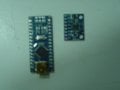
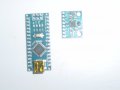
I just found some information online to create a circuit for my needs with a : 3 Axis Gyroscope Acceleromter Module for Arduino DIY MPU-6050 MPU 6050 6D0F and a ATMega 328P Micro Controller CH340G Driver for Arduino 5v 16Mhz Nano V3.0 USB

My question here. Is there anyone here working with Arduino programming? I have the site the creator posted for the "file program" that creates the working circuit.

I know ALMOST NOTHING about the Arduino topic. I do know that you can program it to do what someone wants to perform and it keeps that program stored in it.

I would like to know IF there is anyone in my area; Hamilton, Ontario, Canada, that would be willing to program the Arduino circuit for me? Some kind of fee of course, TBD.

Also, not sure if it matters but the program is in French. So I know nothing about this field, I don't know if that matters.

Please let me now if someone can help me with this. I know you will say it`s a learner field here and I should learn it myself BUT there are personal learner issues I deal with.

Thanks for your Time / Consideration.

George
 

panic mode

Joined Oct 10, 2011
4,973
what is the end goal? what do you want ultimately this to do?
why don't you post the link to example you have? and what do you mean by "program it"? load existing program to Arduino? or write code and load it to Arduino?
and why bother with French code sample when internet is full of examples in English, even English in German accent:
Tutorial: Gyroscope and Accelerometer (GY-521/MPU6050) with Arduino | UATS A&S #12

and if you don't want to, you don't have to learn to write any code yourself... just ask Google AI (or whatever AI you use) to do what you want. it will take some iterations but it works.
 
Last edited:

Reloadron

Joined Jan 15, 2015
7,882
There is the Arduino forum which has a paid help section. They also offer help with code but you are expected to show your attempt at code and specify exactly what you want. There is also a PICAX forum for those using PICAX. Then there is this forum where if you explain your objective in detail help is available. You need to define your objective.

Ron
 

dendad

Joined Feb 20, 2016
4,637
I would encourage you to try this book as it sets things out in an easy to follow step by step way with each line explained.
This ASKmanual has kindly been placed as free on line. It is a bit old but is the one I recommend for new Arduino users.
https://randomnerdtutorials.com/ have loads of help too and is another site I send folk to. They provide free and paid downloadable info and ebooks with very extensive explanations.

It sound like you have a good project and it would be worth you learning to do it yourself as that opens up a world of fun.
https://www.arduino.cc/en/software/ and look for the Legacy IDE (1.8.19) to suit the book or go for the latest version if you like. The user interface is different to that described in the ASK manual..
 

Attachments

Thread Starter

JureGeorge#1

Joined Dec 31, 2025
39
Hello

Thanks for the replies.
To try to clear somethings up.
I have a program from the creator, not me, he created a circuit that controls a pair of dive planes on a model remote control submarine to keep the submarine as level as possible when diving command has been set.
The program he made is in French.
I have the two circuits, I would just like to have the program file loaded/installed into the Arduino circuit. That way I can make a Auto pitch control function for my model submarine.
My computer skills are basic; message boards, ebay shopping, etc.

Here is the link, I hope, for what I have been talking about.
At approx. 2min. see the circuit.

Click onto the: 4.7k 4yrs ago box to see the program.

All I want is someone to load the program into the Arduino circuit I will supply them.

I hope someone in my area can help me with this.

Thanks again
George
 

panic mode

Joined Oct 10, 2011
4,973
I am in Mississauga but work in Burlington. would gladly assist but don't like the rush hour traffic to Hamilton.

loading program to Arduino is trivial and quick job. Are you sure you you don't want to give it a try?
can you post pictures of your exact Arduino (model/version/USB type)?
some variants may not have USB port and need USB to TTL converter for loading program.
 

Thread Starter

JureGeorge#1

Joined Dec 31, 2025
39
I am in Mississauga but work in Burlington. would gladly assist but don't like the rush hour traffic to Hamilton.

loading program to Arduino is trivial and quick job. Are you sure you you don't want to give it a try?
can you post pictures of your exact Arduino (model/version/USB type)?
some variants may not have USB port and need USB to TTL converter for loading program.
First, Thank You for your reply. I can even arrange to meet you in Burlington, hand you the Arduino circuit board for you to install the program then meet you again to pick the Arduino from you. I added a recent picture of the two Circuit boards, two tries at the same picture. for you to see. One question, Does the Arduino board need to be soldered to the other board before the file is loaded into the Arduino OR can I solder the other board, through jumpers, to the Arduino at my bench then power it all up? Also, because of todays times, I have No issues meeting in a public clear space. Please let me know. Thanks, George
 

Attachments

panic mode

Joined Oct 10, 2011
4,973
works for me... don't need headers soldered to program. the USB port is all that is needed. and if you like just bring the headers, i can solder them in no time.
my recommendation is to not solder two modules to each other. it is better to make each of them pluggable and create "motherboard" with sockets for both.

those pictures are showing arduino nano, not sure what vintage or usb connector. my guess is that is Arduino Nano R3 with USB 2.0, mini type B, 5 position (lower left)

1778602404463.png


EDIT....

looks like it is this one:

1778602816264.png
 
Last edited:

panic mode

Joined Oct 10, 2011
4,973
comments are in German, not French.
libraries seem to be:

  • Wire.h: A standard Arduino library used for I2C communication. It is required to talk to the MPU6050 sensor.
  • MPU6050_light.h: A lightweight library used for reading 3-axis gyro and accelerometer data, which computes X and Y tilt angles directly.
  • Servo.h: The standard Arduino library used to control servo motors.
  • ServoInput.h: An interrupt-driven library by David Madison used to read PWM signals, likely for reading input from an RC receiver or reading the position of a servo.

code fixed to use angle brackets, compiles ok:

submarine pitch controller:
// https://www.youtube.com/watch?v=gG0X_yIP1oQ&t=1s

#include <Wire.h>        //angled brackets here
#include <MPU6050_light.h>  //liest direkt Winkel aus
#include <Servo.h>
#include <ServoInput.h>

//Define Variables we'll be connecting to
double Setpoint, Input, Output, Gain1, Gain2;

ServoInputPin<3> TR;                //angled brackets here
//Signal diveplane from receiver to PWM pin 2
ServoInputPin<2> Switch(800, 1800);  //angled brackets here
//switch signal from receiver  PWM pin 3 cal for 3Pos switch Transmitter channel 5 (mc-10)

const int NumPositions = 3;

Servo servoTR;                 
//creates a Servo with the name „servoTR“ =Tiefenruder

MPU6050 mpu(Wire);

void setup()
{
    Serial.begin(9600);
    Serial.flush();
    Wire.begin();
    mpu.begin();
    //Serial.println(F("Calculating gyro offset, do not move MPU6050"));
    //delay(1000);
    mpu.calcGyroOffsets();
    Serial.println("Done.");


    //Input = mpu.getAngleX();
    Setpoint = 100;     //0-Referenz of gyro, approx. in degrees servo arm (0...180)
    Gain1 = 5;     
    Gain2 = 7;     

    servoTR.attach(8); // Servo  signal wire (yellow)  connected to pin 8
}

void loop()
{
    mpu.update();

    float rudder = TR.getAngle();           
// get angle of servo (0 - 180) TR input from receiver

    int position = Switch.map(1, NumPositions);  // get Switch pos 1-3


    if (position ==1)
{
    servoTR.write(Setpoint - mpu.getAngleX() * Gain1);
  }
    else if (position==2)
   {
    servoTR.write(Setpoint - mpu.getAngleX() * Gain2);
   }

    else
  {
    Output = rudder;          // schleift Senderinput durch zu TR Servo
    servoTR.write(Output);
  }


// Serial.print("Switch Position: ");
// Serial.println(position);
//
// Serial.println(rudder);

//
//  Serial.println("\tY: " + String(mpu.getAngleY()));
//    delay(50);
}
1778604646243.png

1778604795938.png
 
Last edited:

Thread Starter

JureGeorge#1

Joined Dec 31, 2025
39
comments are in German, not French.
libraries seem to be:

  • Wire.h: A standard Arduino library used for I2C communication. It is required to talk to the MPU6050 sensor.
  • MPU6050_light.h: A lightweight library used for reading 3-axis gyro and accelerometer data, which computes X and Y tilt angles directly.
  • Servo.h: The standard Arduino library used to control servo motors.
  • ServoInput.h: An interrupt-driven library by David Madison used to read PWM signals, likely for reading input from an RC receiver or reading the position of a servo.

code fixed to use angle brackets, compiles ok:

submarine pitch controller:
// https://www.youtube.com/watch?v=gG0X_yIP1oQ&t=1s

#include <Wire.h>        //angled brackets here
#include <MPU6050_light.h>  //liest direkt Winkel aus
#include <Servo.h>
#include <ServoInput.h>

//Define Variables we'll be connecting to
double Setpoint, Input, Output, Gain1, Gain2;

ServoInputPin<3> TR;                //angled brackets here
//Signal diveplane from receiver to PWM pin 2
ServoInputPin<2> Switch(800, 1800);  //angled brackets here
//switch signal from receiver  PWM pin 3 cal for 3Pos switch Transmitter channel 5 (mc-10)

const int NumPositions = 3;

Servo servoTR;                
//creates a Servo with the name „servoTR“ =Tiefenruder

MPU6050 mpu(Wire);

void setup()
{
    Serial.begin(9600);
    Serial.flush();
    Wire.begin();
    mpu.begin();
    //Serial.println(F("Calculating gyro offset, do not move MPU6050"));
    //delay(1000);
    mpu.calcGyroOffsets();
    Serial.println("Done.");


    //Input = mpu.getAngleX();
    Setpoint = 100;     //0-Referenz of gyro, approx. in degrees servo arm (0...180)
    Gain1 = 5;    
    Gain2 = 7;    

    servoTR.attach(8); // Servo  signal wire (yellow)  connected to pin 8
}

void loop()
{
    mpu.update();

    float rudder = TR.getAngle();          
// get angle of servo (0 - 180) TR input from receiver

    int position = Switch.map(1, NumPositions);  // get Switch pos 1-3


    if (position ==1)
{
    servoTR.write(Setpoint - mpu.getAngleX() * Gain1);
  }
    else if (position==2)
   {
    servoTR.write(Setpoint - mpu.getAngleX() * Gain2);
   }

    else
  {
    Output = rudder;          // schleift Senderinput durch zu TR Servo
    servoTR.write(Output);
  }


// Serial.print("Switch Position: ");
// Serial.println(position);
//
// Serial.println(rudder);

//
//  Serial.println("\tY: " + String(mpu.getAngleY()));
//    delay(50);
}
View attachment 367109

View attachment 367110
Hi, Thanks again. I can solder, that`s Not a problem for me. What Socket assy do you suggest to connect the boards together? Can you show me a link to one? ebay, Sayal. The ONLY specs I have for the two boards is posted in my first posting for this site. Let me know what day/time, location you want to meet to give you the Arduino board. Thanks again.
 

panic mode

Joined Oct 10, 2011
4,973
i do not know your constraints (size for example) and since it is only few wires, i suppose direct soldering is ok.
but i tend to use headers. then each module is easily taken out of circuit or connected again.
those modules are meant to use pin headers 0.1" (male). so the "motherboard" would need to use counterpart - 0.1" sockets like this.

an example of this can be seen here.


or... just use small breadboard like

https://secure.sayal.com/STORE4/prodetails.php?SKU=270412

i prefer soldered connections (much more robust). so i tend to use protoboards like
https://secure.sayal.com/STORE4/prodetails.php?SKU=266948
https://secure.sayal.com/STORE4/prodetails.php?SKU=270651

they sockets are easy to cut to length - just cut through the middle of the "next" contact using flush cutters, then trim the edges using same tool. for example to get 8-position socket for MPU, make a cut on the next (9th) contact.

1778618914908.png

once you have the sockets, solder them onto PCB and then just solder wires as needed onto same board. this way your arduino or any other module are easy to plug in or remove.
 

Thread Starter

JureGeorge#1

Joined Dec 31, 2025
39
i do not know your constraints (size for example) and since it is only few wires, i suppose direct soldering is ok.
but i tend to use headers. then each module is easily taken out of circuit or connected again.
those modules are meant to use pin headers 0.1" (male). so the "motherboard" would need to use counterpart - 0.1" sockets like this.

an example of this can be seen here.


or... just use small breadboard like

https://secure.sayal.com/STORE4/prodetails.php?SKU=270412

i prefer soldered connections (much more robust). so i tend to use protoboards like
https://secure.sayal.com/STORE4/prodetails.php?SKU=266948
https://secure.sayal.com/STORE4/prodetails.php?SKU=270651

they sockets are easy to cut to length - just cut through the middle of the "next" contact using flush cutters, then trim the edges using same tool. for example to get 8-position socket for MPU, make a cut on the next (9th) contact.

View attachment 367125

once you have the sockets, solder them onto PCB and then just solder wires as needed onto same board. this way your arduino or any other module are easy to plug in or remove.
Hi panic mode, Not sure I understand the need for the proto boards. These two circuit boards are only attached to each other via a few wire leads and then a servo is plugged into it with a servo style power wire plugged in and another servo style lead is sent to the radio receiver. That`s ALL the connections I see from the wiring circuit above.
 

panic mode

Joined Oct 10, 2011
4,973
i just mentioned my own preference - but that was just how I like things done and it is not binding - you can use any assembly method that works for you.

my idea is that everything ends up in a single unit (like a lego assembly) instead of individual modules.
"lego" style modules can be plugged and unpluged many times in seconds without any tools.

an example of using breadboard as carrier. here all things plug into breadboard (modules, interconnecting wires, cables to external devices...)
this is quick and easy to rearrange as needed. disadvantage is that connections are not very sturdy making it not very portable:
1778643908311.png


the same thing can be assembled using "proper PCB". modules still plug into sockets. this is more compact and interconnects are more robust. the downside is that one need to design and make such PCB. in this picture blue units are modules that simply plug into carrier board. black PCB in the background is the custom carrier board.
1778643802818.png


for quick one off design, one can use some sort of protoboard like the ones i linked before.

if modules are not assembled together into one unit like above examples, they need to be mounted on some non-conductive support individually, without stressing the wires. this is robust as mounting of each module is ensured through some mechanical means (using hot glue, screws, whatever). the disadvantage is that soldered connections, separate mounting of each module and soldered connection mean slower access and need for more tools (including soldering iron) to separate them if there is a need to troubleshoot or tweak the circuit. and reconnecting need to be donecarefully, keeping track where each wire goes. this is much slower than simply pulling module out of board.

images in this post are taken from someone else's video. you can see how easy it is to plug modules into custom PCB at 40sec mark.
 
Last edited:
Top