Custom Atmega328-P (Arduino) Circuit HELP

Thread Starter

Brent1798

Joined Jun 5, 2018
17
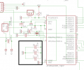
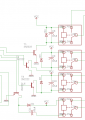
Hello! My name is Brent Carroll. I have already come a far way with my design and schematic, but some problems are arising that I simply don't know how to fix. I have a circuit that uses an Atmega328-P (the same one used on Arduino) and I have 4 relays attached to it as well and an LCD, some sensors, and 3 buttons. My problem is that when I ask it to open 2 or more relays, the circuit resets. I hear that this is caused by a drop in amps or sometimes signal noise from the relay, but I added a flyback diode to cancel that noise so I am lost as to what is happening. Can anyone help?

circuit.png

board.png

Moderators note : removed the double pictures
 
Last edited by a moderator:

AlbertHall

Joined Jun 4, 2014
12,346
In your diagram the regulator GND and output pins are swapped. I hope they are not really wired like that.
What is the coil resistance of the relays?
 

jpanhalt

Joined Jan 18, 2008
11,087
I do not see many decoupling capacitors. Do you have them, but don't show them? When activating 2 relays simultaneously, that current drain could be making VCC drop and cause a reset. Some people recommend 10 uF parallel with 1 uF or 0.1 uF or even all three from VCC to ground as close as practical to the VCC pin(s) of the MCU. You might also put a larger one (47 uF to 100 uf) across each relay.
 

be80be

Joined Jul 5, 2008
2,072
These are way to high and will pick up noise
Screenshot from 2018-06-05 15-33-54.png

Plus it's always better to power relay's from main supply before regulator.
The 5 volt relays are nice but 4 of them from your uC supply is asking for problems.
 

Thread Starter

Brent1798

Joined Jun 5, 2018
17
In your diagram the regulator GND and output pins are swapped. I hope they are not really wired like that.
What is the coil resistance of the relays?
Yeah, I had to wire it like that because the pins on the actual surface mount part are swapped around a bit.
The coil resistance is 22.5 Ohms.
 

jpanhalt

Joined Jan 18, 2008
11,087
You have analog VCC and everything else VCC. Noise on VCC(digital) can cause a reset. Try decoupling first. Powering the relays from the unregulated source before the voltage regulator might also help.
 

Thread Starter

Brent1798

Joined Jun 5, 2018
17
I do not see many decoupling capacitors. Do you have them, but don't show them? When activating 2 relays simultaneously, that current drain could be making VCC drop and cause a reset. Some people recommend 10 uF parallel with 1 uF or 0.1 uF or even all three from VCC to ground as close as practical to the VCC pin(s) of the MCU. You might also put a larger one (47 uF to 100 uf) across each relay.
How does this look for the "recommend 10 uF parallel with 1 uF or 0.1 uF or even all three from VCC to ground as close as practical to the VCC pin(s) of the MCU"

And I suppose 68 is an acceptable value for the caps across the relays?
 

Attachments

Thread Starter

Brent1798

Joined Jun 5, 2018
17
You have analog VCC and everything else VCC. Noise on VCC(digital) can cause a reset. Try decoupling first. Powering the relays from the unregulated source before the voltage regulator might also help.
I just recently added some decoupling capacitors. Does this fit?
 

Attachments

be80be

Joined Jul 5, 2008
2,072
I use 12 volt relays and wall wart then step down the the 12 volt for my uC
the arduino ADC works way better at below 25K the 100k on the ground will pick up everything

The ADC is a kind of like a cap it charges up and then read's the value if you put a 100 k it will not not read as fast as it should so any little spikes will start showing up over time.
The 100 k will show stuff it would see not the stuff you want it to read in a nut-shale
 

jpanhalt

Joined Jan 18, 2008
11,087
I just recently added some decoupling capacitors. Does this fit?
Yes. They need to be close to the VCC pin when actually connected. Sometimes they are omitted from the main schematic or shown in a separate area, which was the basis of my original question.

You may not need a cap across the relays, if you have decoupling. Then I'd try powering the relays pre-voltage regulator. They are not as sensitive to VCC as the MCU is.
 

AlbertHall

Joined Jun 4, 2014
12,346
The coil resistance is 22.5 Ohms.
At 5V that's 220mA per relay and that regulator is specified for 200mA so it's hardly surprising 2 or more resets it.
You will need to power the relays ftom the input power and then the relays will need to be a suitable coil rating for the input voltage. Higher coil voltage relays will also draw less current.
 
Hi Brent1798,

I notice that your circuit has no resistors between the ATMEGA 328 I/O lines, pins 1,2,10,11, and the 2N2222 bases.
This will prohibit these lines from ever going above 0.6v.
I would use some 2k7's here, which would allow those lines to reach "digital high".
 

Involute

Joined Mar 23, 2008
106
See the attached app note for the proper hardware setup for an AVR, and the reasons why, though the other comments here are spot on. Also, for schematic clarity, isolate the regulator somewhere else on the schematic (doesn't have to be a separate sheet), with its output going to VCC. Then anything else that needs to connect to VCC can just reference that, including an up arrow. It also clears things up if you can arrange signals to flow, as much as possible, from left to right through the schematic
 

Attachments

danadak

Joined Mar 10, 2018
4,057
If the Atmega during power up tristates its output you need to add a R to gnd
at NPN relay driver to insure it stays off, that leakage will not turn it on. Here is
a representative circuit.


The base R is calculated R1 << Vbe / Ileak.

Ignore LED and R4, just an image I found on web serving as example.

Regards, Dana.
 

danadak

Joined Mar 10, 2018
4,057
FYI -

"When a AVR chip goes through reset, like just before a new sketch is being uploaded to it, the first thing that happens is that all I/O pin are set as input pins, so anything you have wired to them will see a 'floating' voltage."

Regards, Dana.
 

Flemo

Joined Oct 23, 2016
2
I believe that the last cct diagram and feedback from Danadak is a great suggestion, I would only think to change the Value of R1 down to something less than R2 value by at least 7 or 8 times lower. This way R1 acts as a pull down for when Reset is applied to the micro and your relays will not energise during the startup process.
 

miomir1981

Joined Nov 30, 2010
2
Few members wrote this already in their posts. Put a resistor between pins that are driving your transistors and base of those transistors. The reason why one relay is working, and when you switch the other one, circuit resets, is that you microcontroller outputs alot of current into the base of the bipolar transistors. See, base emiter junction behaves like a diode, with its threshold voltage of 0.7V. When you apply Vdd (high) voltage to the base of the transistor, it pulls alot of current. When two of this are switched on, your microcontroller or the LDO can't handle it and it causes the reset.

Also, as @danadak said, it is good to have some puldown resistor with higher value than driving resistor between ground and base just in case your pin is floating. For bipolar transistors, this is not needed, cause they need current to drive them. But situation changes if you try to use N type MOSFET. They should never have their gate floating, so use the pulldown resistor in that case. Also, if you are using MOSFET, use resistor between microcontroller pin and gate. Gate requires charge to be acumulated on the gate in order to be switched on. Charge needed depends on how big gate of the transistor is. This charge comes from the curent supplied by microcontroller pin. So, if you don't limit this current with a resistor, you will have a high current spike which can cause microcontroller to reset or damage the pin ireversably. Of course, this will slow down the switching time by a very small amount of time (millisecond maybe), but it will be a good tradeoff for saving the microcontroller pin.
 
Top