 Facebook
 Google
 GitHub
 Linkedin
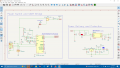
This personal project is my first attempt at designing the schematic of a custom microcontroller-based circuit board. I based this design around STM32's B-L4S5I-IOT01A discovery board. However, I still have a few doubts regarding the functionality of this design, especially when it comes to the power delivery and the SWD pins.
I wanted to ensure this board is capable of being powered by an external battery that is at least 5V, or the 5V from my PC's USB port. I also made sure a switch would decide which power source would supply the microcontroller. I wanted to include the possibility of an external battery to make this circuit portable and not entirely dependent on USB unless I wanted to debug it.
The issue I have with the power delivery is that I'm not sure if I included the proper circuitry to make it work once it is physically powered. I'm not sure if the micro-B USB pins are correctly connected. Compared to the discovery board's schematic, I had to simplify it, since I only want it to supply power and allow UART communication with the MCU through the CP2102 component for debug purposes.
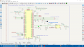
I also wanted to make sure this board is programmable, so I exposed the relevant SWD pins from the MCU. I am planning on using the detachable ST-Link programmer from a NUCLEO board. After a bit of reading online, I'm still not sure whether I need to also connect the programmer's VDD pin to the circuit board. And I'm not sure if I should I also power both the programmer and the board simultaneously when flashing a program.
Before starting the PCB layout of this schematic, I thought it would be useful to have an extra pair of eyes look at it to point out any obvious mistakes that I may have missed. I would appreciate it.
I wanted to ensure this board is capable of being powered by an external battery that is at least 5V, or the 5V from my PC's USB port. I also made sure a switch would decide which power source would supply the microcontroller. I wanted to include the possibility of an external battery to make this circuit portable and not entirely dependent on USB unless I wanted to debug it.
The issue I have with the power delivery is that I'm not sure if I included the proper circuitry to make it work once it is physically powered. I'm not sure if the micro-B USB pins are correctly connected. Compared to the discovery board's schematic, I had to simplify it, since I only want it to supply power and allow UART communication with the MCU through the CP2102 component for debug purposes.
I also wanted to make sure this board is programmable, so I exposed the relevant SWD pins from the MCU. I am planning on using the detachable ST-Link programmer from a NUCLEO board. After a bit of reading online, I'm still not sure whether I need to also connect the programmer's VDD pin to the circuit board. And I'm not sure if I should I also power both the programmer and the board simultaneously when flashing a program.
Before starting the PCB layout of this schematic, I thought it would be useful to have an extra pair of eyes look at it to point out any obvious mistakes that I may have missed. I would appreciate it.
Attachments
-
 141.5 KB Views: 22
 -
 167.6 KB Views: 23

")


