Schematic Review Request for Capacitive Soil Moisture Sensor

Thread Starter

NerdyCrafter

Joined Aug 6, 2025
5
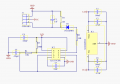
I recreated this based on standard capacitive soil moisture sensors on the market. I want to make my own as they are often poorly manufactured and have the wrong components. I've read a lot of different material on forums online, there is a lot of debate about different resistor values, etc. I will then connect this to whatever MCU I decide connecting, ground, 3v for power, and AOUT.

I'm a noob so please bare with me if I made any obvious mistakes. :) I'm ready to learn, and greatly appreciate any feedback or suggestions.

Screenshot 2025-08-06 144219.png
 
Last edited by a moderator:

Ian0

Joined Aug 7, 2020
13,112
Where did you get that circuit? I can't see how it can possibly measure the capacitance between the probes as you have already got 1uF across the probes, and the change in capacitance is likely to be many orders of magnitude smaller than that.
It looks more like it measures the resistance between the probes, not the capacitance.
 

boostbuck

Joined Oct 5, 2017
1,037
If this is the circuit you are trying to use, you have drawn the probe on the wrong side of the diode:

1754549252403.png

It does seem that the measurement is voltage of simple resistive divider of the pulsed output, smoothed with the 1uf .
 

Thread Starter

NerdyCrafter

Joined Aug 6, 2025
5
Thanks for pointing that out! I don't know how I missed that. This is the one I'm trying to copy/improve(if there are any improvements to be made). I'm using the TLC555 instead so that it will run on 3V, the project will run on battery hence the need for the voltage regulator so it remains steady.
 

Attachments

schmitt trigger

Joined Jul 12, 2010
2,056
Excellent project. Please keep us posted if your progress.

BTW, I also agree that a Schottky diode would work better at such low supply voltage.
Use a BAT54.
 

boostbuck

Joined Oct 5, 2017
1,037
The circuit described cannot work. Its a simple hoax designed to impress the uninformed.

In the video, the squarewave circuit is said to be converted into a constant voltage by the diode and 1uf cap.

So what is the purpose of the square waves if the probes have a smoothed voltage applied? A simple voltage source (eg the regulator in the circuit) would suffice.

If the voltage applied to the probes is constant, there is no applied change to measure the capacitance value of the soil moisture.

If the soil capacitance WAS being measured in some fashion by the probe described, the capacitance change would be in the order of picofarads. But the probe is in parallel with a capacitor of value 1,000,000 pf (1uf), overwhelming any moisture value.

Therefore, as Ian has said, it MUST be a resistive divider and its operation is then prevented by the probes being insulated. If it does work in any fashion that must be due to failure of the probe insulation.
 

boostbuck

Joined Oct 5, 2017
1,037
In fact, the circuit I posted in #3 appears to be a square-wave driven resistive divider with a voltage-smoothing 1uf load on the output, a much more workable circuit.

It's my understanding that the use of square waves to drive the probes is to reduce cathodic corrosion, although that would surely require voltage reversal, which the circuit in #3 doesn't appear to achieve.
 

Ian0

Joined Aug 7, 2020
13,112
If you look at other circuits on the internet, then the probes are BEFORE the diode, which means that it could measure capacitance: on a pure capacitance, the peak-to-peak voltage of the triangle-wave produced across the probes would be inversely proportional to the capacitance and the diode and 1uF form a peak detector to measure it. However, it would be adversely affected by any resistance across the probes. It is easy to tell whether it is measuring pure capacitance - the output voltage would never fall below half supply less the diode. All the videos show the output going to zero, so it's not measuring capacitance.
It could be improved by capacitively coupling the squarewave to the probe and using an emitter follower as the peak detector. It still leaves the output impedance at 1MΩ, set by the output resistance, so it is probably really measuring the leakage resistance across the output leads.
That could be buffered by another emitter follower, to give a low output impedance, but now it's getting complicated.

The designer seems to have completely overlooked the easy and simple way of measuring capacitance: Use the capacitance as the timing element in a 555 circuit and measure the output frequency. The probes could have 1uF in series to remove any DC offset without affecting the result.
If the squarewave were buffered by an inverter to give a differential signal, it could be driven miles without affecting accuracy.

Having said all this, I wonder if we would in reality be capacitively measuring the thickness of the solder resist
 
Top