Facebook
 Google
 GitHub
 Linkedin
Hi everyone,
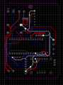
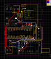
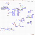
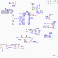
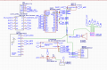
I am currently working on a flight computer design for a student rocketry competition . I would like to get some feedback on my PCB layout and schematic before I send it to production.
I am currently working on a flight computer design for a student rocketry competition . I would like to get some feedback on my PCB layout and schematic before I send it to production.
Attachments
-
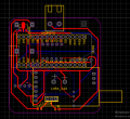 88.9 KB Views: 49
 -
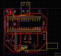 81.1 KB Views: 49
 -
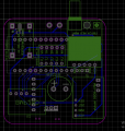 81.6 KB Views: 43
 -
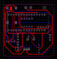 66.2 KB Views: 42

")