 Facebook
 Google
 GitHub
 Linkedin
Hi All,
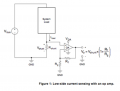
I am having difficulty with an op amp circuit that I am building.
I am using a LA6500 op amp attached in parallel with a 0.1ohm shunt resistor. See attached circuit design.
This is a 12V DC circuit.
Purpose of amplifier is to power an LED when there is current through the circuit and turn off when there is no current.
Amplifier works fine when there is current through the circuit.
Using the circuit attached. I am using Rf = 68000ohm and Rg as 8200ohm. Voa is coming from the circuit before the load.
When I break the circuit between the load and the shunt resistor(dropping voltage across the shunt resistor to 0) the op amp gives max output voltage.
Any help would be appreciated,
Thanks,
Peter
Attachments
-
 79.2 KB Views: 52


