I have to go to bed.....It's 00:50 my time Ireland.
I very much appreciate your and audio guru and alls help.
But I got to get up in 5 hrs, I have learned a lot these last couple of nights, talk again thanks
Why reduce the opamp's supply voltage? It has a low output current then it does not get hot. Its absolute maximum allowed supply voltage is 44V. It is the TIP41 transistor and output transistors that have the high current and any extra voltage above about 17V makes them very hot.
If you had the reference connected to the non-inverting input and the rest of the circuit was "right" it should not affect stability. Your voltage reference is stable to within 100 parts per million per °C. The voltage drop across the 2N2222 is about 2 millivolts/°C of the 5V reference for 400 parts per million per °C. In other words, you are cheating yourself out of the thermal stability you paid for the LM1440 by adding that transistor's thermal dependency.
The last time I saw something like that it turned out that were was a ground loop that affected the feedback.
If you had the reference connected to the non-inverting input and the rest of the circuit was "right" it should not affect stability. Your voltage reference is stable to within 100 parts per million per °C. The voltage drop across the 2N2222 is about 2 millivolts/°C of the 5V reference for 400 parts per million per °C. In other words, you are cheating yourself out of the thermal stability you paid for the LM1440 by adding that transistor's thermal dependency.
The last time I saw something like that it turned out that were was a ground loop that affected the feedback
Hello, thanks Sghioto, Audioguru, DickCappels and all for your help
You got me thinking DickCappels, Very interesting.
I have had a good look at my wires and copper connectors, I took them apart and cleaned with isopropanol, same result. I attached a crocodile clip with a heavy cable from the neg of the board to the neg terminal post at the front, and I got less drop.
I made new leads powering the board and vr2 to neg (large .12" diam. multistrand) with soldered eyelets.
Better still a small drop, I then altered zener drop resistor to 4.4k after experimenting.
I was reading again yesterday about non-inverting op-amps and feedback resistors, and the relationship between vr1 and vr2, about the important thing is the ratio between these two, and the fact that they can be altered up or down in value but the outcome will always be the same so long as the ratio is kept the same, but the current travelling through the op-amp reduces if they are increased. So if I increase them will it reduce the workload of the op-amp?.
I doubled them vr1 10k and vr2 10k.
The result.......Could not be better. No drop on both 2Amp and 4Amp load....what the ??
Still thinking about lowering the voltage and maybe lowering the reference voltage.
I am only testing with a 4 digit multimeter, the led voltmeter I put on the front is inaccurate.
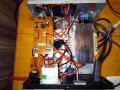
Attached photos of new layout, my work in progress unit and the Altai unit
Glad to see it you got it working better.
Not sure if I would lower the reference voltage unless you want to go below 4 volts on the output.
Only other recommendation would be to replace the two 10K pots with a single 20K. Center tap to -input.
Glad to see it you got it working better.
Not sure if I would lower the reference voltage unless you want to go below 4 volts on the output.
Only other recommendation would be to replace the two 10K pots with a single 20K. Center tap to -input.
See diagram about the pot.
Reducing the voltage to the output transistors will lower their power dissipation. It depends on the maximum output voltage you require.
As you have it designed now I calculate the dissipation on Q2,Q3 at appx.18 watts each at 4 amps. Based on a 12 volt output and the input voltage dropping to 21 volts at 4 amps to be exact. Q1 at appx .6 watt.
Noticed an error in your schematic. The collectors of Q1-Q3 should be connected together.
Q2,Q3 are rated 150 watts and properly heatsinked should not be a problem.
I don't think so but you probably could just use one of the10K pots you have now. Adjusting the one pot will get you the same ratio of 1.4 somewhere in it's range.
I don't think so but you probably could just use one of the10K pots you have now. Adjusting the one pot will get you the same ratio of 1.4 somewhere in it's range.
One thing I noticed today, you might throw some light on it.
If I limit my voltage range to say 5-14v by adjusting vr1 I get no drop, if I increase this range to say 18v I get a slight drop creeping in, is this a tiny drop at pin 3 multiplying
Any drop at pin 3 is going to show up on the output. However a 18 volt output requires the output of the chip to be 19.4 volts. If the supply is dropping to 21 volts there may not be enough "overhead" to sustain a 18 volt output. The specs indicated the max output of the chip is the supply voltage minus 1 volt.
Any drop at pin 3 is going to show up on the output. However a 18 volt output requires the output of the chip to be 19.4 volts. If the supply is dropping to 21 volts there may not be enough "overhead" to sustain a 18 volt output. The specs indicated the max output of the chip is Vcc+ minus 1 volt.
I know this is a silly question, how do you arrive at an exact 1.4 v loss at 19.6v
Silly question no.2 would connecting two power diodes in series drop the 23v by 1.2v, i'm trying to reduce the heat dissipation in q2,q3
The output from the chip goes through two base emitter junctions. Q1 and the parallel combo of Q2,Q3. You lose appx .7 volt per junction. Just as you lose voltage through diodes, same principal.
Yes it would or more depending on the current. At 4 amps that would dissipate appx 4.8 watts. dropping the transistor dissipation to under16 watts per transistor at 12 volt out.
At 12 volts and 4 amps you have a total dissipation of appx 36 watts, 18 watts per transistor. Whether you add series diodes or resistors there is still a total of 36 watts in the form of heat that must be dissipated.
Since the transistors are rated at 150 watts, mounted on a proper heatsink and fan cooled as I believe you mentioned earlier I don't see the need for the extra components.
The common mode voltage range of only 2.9V is when its supply is only 5V. When the supply is +/-15V then the common mode voltage range is -15V to +12.9V. The bases of its PNP input transistors stop working then they are higher than 2V below the positive supply voltage like the PNP input transistors in an LM324 and LM358.
The common mode voltage range of only 2.9V is when its supply is only 5V. When the supply is +/-15V then the common mode voltage range is -15V to +12.9V. The bases of its PNP input transistors stop working then they are higher than 2V below the positive supply voltage like the PNP input transistors in an LM324 and LM358.
I only got a chance to try out the previous suggestion of combining vr1 and vr2 into one 10k, and then 20k by Sghioto today. Happy holidays.
The 2 amp load is a car light bulb, really 1.75 amp to be exact.
The 4 amp load is a 12v halogen bulb rated at 50watts
The halogen bulb draws 4.5amps at 13v to 15v and 5amps at 15v to 16v
10k and 20k......5 to 12v no voltage drop on 2 and 4 amp
10k 4amp
13v 10mv increase (drawing 4.5amp on ammeter)
14 v 20mv increase ,, ,,
15v 30mv increase (drawing 5 amp on ammeter)
16v 150mv increase ,, ,,
20k 4amp
13v 20mv increase (current draw same as above)
14v 30mv increase
15v 30mv increase
16v 800mv increase
Both similar to about the 15v mark, both show a large increase at 16v, another point an increase in voltage rather than drop.
Is @14volts drawing 4amp the achilles heel for this design (23v supply and only 2 power transistors)?
I remember reading that your transformer needs to be at least 1.5 times your required output voltage to allow for the inefficiency of a linear power supply?.
The metal box has a label stating 13.8v 5amp continuous 7amp 50% duty cycle, I am using the same transformer that is in the unit.
 Facebook
 Google
 GitHub
 Linkedin
![IMG_20201222_201947[1].jpg](/data/attachments/213/213290-162923566401cc38a2f4e35ad04611ad.jpg)