 Facebook
 Google
 GitHub
 Linkedin
Hello Good people,
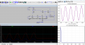
I have a question regarding the biasing of a second order Sallen-Key low pass filter. The filter seems to work fine when I use a sinusoidal input in LTSpice and produces an output centered around 1.65V. However when I give it some random test data (top right image), the output waveform is not centered around 1.65V, but is rather shifted downwards.
Could someone guide me on why this happens with my test data and not with the sinusoidal input functions in LTSpice ?Any suggestions to look into would be really helpful.
Attachments
-
 155.1 KB Views: 26


