V divider rule stopped working when biasing a transistor

Thread Starter

tpny

Joined May 6, 2012
220
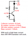
How come this circuit operates differently (lights up/dims) depending on the npn transistor used??

When using:
npn = 2n4401, LED = ON, base = 0.7V
npn = 3904, LED = OFF, base = 0V

More confusingly, why does it light up at all? If the base reads 0.7V, then doesn't the voltage divider rule (between 560 and 5k resistor) completely COLLAPSE!! How can this happen??

Rich (BB code):
                      5v
                        |
       |----------------|
     |            |
       |            150
     560             |
       |               |
       |              /
       |------------|/ npn
       |            |\
       |               \
     5K              |
       |               |
       |               |
       |---------------|
                       |
                     gnd
 

JMac3108

Joined Aug 16, 2010
348
Well the quick answer is that you don't just have a simple voltage divider. You have current flowing into the base of the transistor that changes your voltage divider.

If you have base current flowing and the transistor turns on, the emitter is at ground, so the base is going to be at about 0.7V due to the base-emitter drop of the transistor.
 

JMac3108

Joined Aug 16, 2010
348
I don't have time right now to explain how to design a reliable transistor switch. Maybe someone else can do this.

Basically you need to know how much collector current is required for your load, then divide this by the minimum beta of the transistor, and setup your base circuit to ensure that it drives this much current or more. THis ensures that you always have the transistor in saturation when its turned on.
 

ScottWang

Joined Aug 23, 2012
7,409
If you use LED series in C with 150R, because the Rbe just a little affected for Vbe, it should be every NPN transistor can light up the LED, so I think you had made a mistake about the c,b,e pins when you testing.

You just try it again.
 

Audioguru

Joined Dec 20, 2007
11,248
Basically you need to know how much collector current is required for your load, then divide this by the minimum beta of the transistor, and setup your base circuit to ensure that it drives this much current or more. THis ensures that you always have the transistor in saturation when its turned on.
No.
The datasheet of almost EVERY transistor shows its saruration voltage loss when its base current is 1/10th the collector current. Beta is not even mentioned.
 

Audioguru

Joined Dec 20, 2007
11,248
I don't draw awful schematics using text. Instead I simply use Microsoft Paint program.

The base current is so high at nearly half the collector current then ANY transistor will work.
 

Attachments

cabraham

Joined Oct 29, 2011
82
The 5 kohm resistor across base to emitter is shunted by the input resistance of the b-e junction. This resistance is much lower than 5 kohm, so you cannot compute Vbe simply as the divider ratio of 560 ohm & 5 kohm. A good start is to observe the LED lamp OEM recommended forward current. This can be 20 mA for most low power LED lamps. Allowing 0.20V for the Vce saturated value, & 2.0V for the LED voltage forward drop, we have 2.8V across the collector resistor. So, 2.8V/20mA = 140 ohm for Rc. Standard 5% values are 150 ohm, & 160 ohm. If you want 1% values, 140 ohm, & 147 ohm will work. The 2.0V forward drop for the LED can vary. For IR it is 1.5V or less, 1.8V for red, & if the LED is a high power green or blue, it can be 3.5 or 4V. I just used 2.0V as an example.

For the base drive, nearly all small signal bjt data sheets spec their saturation at a "forced beta" of 10, i.e. Ib = Ic/10. In this case the base drive target value is 20 mA / 10 = 2 mA. Since Vbe = 0.70V, the resistance value is (5.0-0.7)/(2.0) = 2.15 kohm. This value is a standard 1% offering. For the resistor across the base-emitter input, 10 kohm should work well. It will draw 0.07 mA which means that the base drive will be 1.93 mA, which is sufficient. You may, if you wish, drop the 2.15 kohm resistor down to 2.05 kohm, which assures 2.0 mA in the base terminal of the bjt.

Just off the cuff, this is the approach taken for such an application. When using a bjt as a switch, not an amplifier, the idea is to assure saturation. When the "forced beta value" is well below the worst case minimum beta value for the part, saturation is assured. Since a small signal device, such as a 2N3904, 2N4401, 2N2222A, etc. has a beta value of 100-250 typical, decreasing to 80 or 60 at low temperature & with specimen variations, a forced beta value of 10 assures saturation. So any bjt device with a beta a lot greater than 10 should give great results.

I hope this treatise has been helpful. I will clarify if needed. BR.

Claude
 
Last edited:

JMac3108

Joined Aug 16, 2010
348
Audioguru,

We're making the same point, just different ways. To make sure the transistor is in saturation, you make sure that you drive a base current that would generate a collector current that ensures that the transistor is in saturation, given the voltage drop of the LED and the collector resistor value. Best explained with an example.

A simple example of a very simple design process for an NPN transistor switch to turn on an LED ...

Specs: 5V PS, LED with 2V forward drop, 10mA current through LED, transistor with minimum beta 50. Need to turn on/off the LED with micro-controller with 3V logic level.

Design process:

(1) I'm going to assume VCE(sat) is negligible, then the collector resistor is Rc=(5V-3V)/10mA=200ohms.

(2) The required base current is Ib=Ic/beta(min) = 10mA/50 = 0.2mA. I'm going to double this to make sure that transistor is in saturation, therefore I want 0.4mA base current.

(3) The base resistor has 3V from the micro-controller on one side, and 0.7V at the base of the transistor on the other side, so to get 0.4mA I need a resistor of, Rb=(3V-0.7V)/0.4mA=5.75K. I'll choose the nearest standard value ... better yet, I look at the rest of my design and see that I have lots of 4.7K pull-up resistors on my board. So I'll use that value. This gives me a base current of Ib=(3V-0.7V)/4.7K=0.49mA.

Now I have a simple transistor switch that is guaranteed to be in saturation when turned on. And the collector current will be very close to the desired 10mA, the only error being the fact that I did not include VCE(sat) which is small and will not significantly affect the end result.
 

JMac3108

Joined Aug 16, 2010
348
I should have read Cabraham's explanation in detail before I wrote mine. He said it much better than me. Our approaches are the same, but he has more detail and used better real-word numbers. :D

Bottom line is that you make sure that the base current is large enough to ensure that the transistor saturates given the minimum beta of the transistor and your collector load.
 

Audioguru

Joined Dec 20, 2007
11,248
No again.
The beta for many transistors is spec'd when the transistor is a linear amplifier with plenty of collector to emitter voltage (typically 10V) so it is NOT saturated.

A 2N5089 transistor has a minimum beta of 450 when its collector current is 10mA and its collector to emitter voltage is 5V so it is not saturated. But its saturation voltage loss is spec'd when its base current is 1/10th its collector current like millions of other transistors.

The beta drops very low when a transistor is saturated so beta is not used.
 

Thread Starter

tpny

Joined May 6, 2012
220
The 5 kohm resistor across base to emitter is shunted by the input resistance of the b-e junction. This resistance is much lower than 5 kohm, so you cannot compute Vbe simply as the divider ratio of 560 ohm & 5 kohm. A good start is to observe the LED lamp OEM recommended forward current. This can be 20 mA for most low power LED lamps. Allowing 0.20V for the Vce saturated value, & 2.0V for the LED voltage forward drop, we have 2.8V across the collector resistor. So, 2.8V/20mA = 140 ohm for Rc. Standard 5% values are 150 ohm, & 160 ohm. If you want 1% values, 140 ohm, & 147 ohm will work. The 2.0V forward drop for the LED can vary. For IR it is 1.5V or less, 1.8V for red, & if the LED is a high power green or blue, it can be 3.5 or 4V. I just used 2.0V as an example.
Wow this is really clear!

I guess it makes NO sense to put the 5k (or any Rbe) resistor when all you want is to use the transistor as a switch. The voltage divider at base makes no sense when all you need is an Rb.
 

Thread Starter

tpny

Joined May 6, 2012
220
By the way, it turns out my 3904 is trashed. I replaced the 3904 and the led lights up as well (like scottwang said it should).
 

JMac3108

Joined Aug 16, 2010
348
Audioguru,

I learn something new everyday! You are correct, I have not been careful enough when using BJT datasheets to note that hfe is spec'd with a VCE that places it in the linear range. Given this, the minimum hfe on the datasheet is not relevant when designing a BJT switch.

I checked a couple datasheets and indeed, most had hfe specified with VCE=10V. And as you said, most speficied VCE(sat) at Ib = Ic/10.

For design purposes, you could consider the minumum hfe for saturation to be 10, since VCE(sat) is specified at Ib=Ic/10 which is a current gain of 10, and use the graph of VCS(sat) vs IC in the datasheet. I looked at a Fairchild 2N2222 datasheet and they give a graph of VCE(sat) vs. IC, at beta=10. See attached.

Thanks AudioGuro for pointing this out.
 

Attachments

Audioguru

Joined Dec 20, 2007
11,248
The graphs on a datasheet are for a "typical" device. But you cannot buy a "typical" device, instead you get whatever they have which might be maximum or might be minimum.

Your Fairchild graph shows a 500mA collector current and a very high base current of 50mA then shows a "typical" collector to emitter saturation voltage of less than 0.3V at room temperature. But the spec's say its maximum collector to emitter saturation voltage using the same spec's is a maximum of 1.0V which is much higher.
 

JMac3108

Joined Aug 16, 2010
348
Yep. Same thing at the Ic=150mA point ... graph shows a typical VCE(sat) only a little more than 0.1V, but the datasheet lists the worst case as 0.3V.
 

Austin Clark

Joined Dec 28, 2011
412
To clarify, do you guys mean to say that Beta is meaningless when in saturation, because beta can't be reliably calculated because the collector current is as high as it can go at that point? Basically, Beta is used to find when you'll be in saturation, but once in saturation Beta is "capped".
 

Audioguru

Joined Dec 20, 2007
11,248
Look at the datasheet for ANY transistor like a 2N2222A. Its beta (hFE) is spec'd when it has a collector to emitter voltage of 10V SO IT iS NOT SATURATED.
Then look at the spec of its maximum saturation voltage. Its base current is a whopping 1/10th of its collector current.
 

Attachments

Top