Old SCR Night Light devices and LED Bulbs

Wendy

Joined Mar 24, 2008
23,803
Have successfully converted xmas accessories like a tree top angel from old incandescent bulbs to leds using discrete components by doing some math but am not seeing a clear way to modify these simple one scr ldr night light circuits simply because the led bulbs are an unknown ... does anyone have a simple solution to reusing these devices with led bulbs? Or know how to model these 7W Led bulbs to do calculations
So your wanting to learn about SCRs? or make an LED circuit? Perhaps you need to clarify your request. Because right now it feels shifting sand.
 

Thread Starter

bxdobs

Joined May 11, 2014
32
Thank-you for all the replies ... retired life seems to be busier than normal ... thought I had flagged this thread for email notification but haven't received any email notifications which is why I haven't returned to the site until now.

Wasn't looking to start a row ... reading between the lines, the feedback suggests that my original wording was too vague ... so let me try this again ... hopefully those of you that have nothing to offer can just remain silent

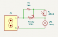
These are stock C7 7W night light (for incandescent bulbs) devices that plug in to 120VAC NA outlets ... they have a po102 SCR with the gate controlled by a 3M6 and LDR (voltage divider) ... this circuit is designed for incandescent bulbs because they provide a short to N when the SCR is off ... LED C7's don't look like a short ... during the day, C7 LED bulbs visibly flicker at 60 Hz and at night they are on full brightness ... so still kind of work but would like the bulbs to turn off during the day
Capture.PNG

I am not a fan of e-waste ... there is plenty of space within these housings so just reached out to see if someone can shed light on a way to incorporate a better off scenario for the LED C7 bulbs using a simple LDR circuit ... I have a plethera of parts and 40+ years of electronic design experience ... C7 Led bulbs are meant to be used in 120VAC sockets so in order to start a design for them one has to understand their on and off characteristics. Which was what I was kind of asking for ... specifically if anyone had knowledge regarding these new Led Bulbs they would be willing to share.

Thanks again
 

MisterBill2

Joined Jan 23, 2018
27,980
An experiment could be a capacitor in series with the LDR to provide some phase shift. Or it might need to be across the trigger gate pull-down resistor. But certainly the design needs a phase shift.
 
Thank-you for all the replies ... retired life seems to be busier than normal ... thought I had flagged this thread for email notification but haven't received any email notifications which is why I haven't returned to the site until now.

Wasn't looking to start a row ... reading between the lines, the feedback suggests that my original wording was too vague ... so let me try this again ... hopefully those of you that have nothing to offer can just remain silent

These are stock C7 7W night light (for incandescent bulbs) devices that plug in to 120VAC NA outlets ... they have a po102 SCR with the gate controlled by a 3M6 and LDR (voltage divider) ... this circuit is designed for incandescent bulbs because they provide a short to N when the SCR is off ... LED C7's don't look like a short ... during the day, C7 LED bulbs visibly flicker at 60 Hz and at night they are on full brightness ... so still kind of work but would like the bulbs to turn off during the day
View attachment 340731

I am not a fan of e-waste ... there is plenty of space within these housings so just reached out to see if someone can shed light on a way to incorporate a better off scenario for the LED C7 bulbs using a simple LDR circuit ... I have a plethera of parts and 40+ years of electronic design experience ... C7 Led bulbs are meant to be used in 120VAC sockets so in order to start a design for them one has to understand their on and off characteristics. Which was what I was kind of asking for ... specifically if anyone had knowledge regarding these new Led Bulbs they would be willing to share.

Thanks again
I suspect at least part of the problem is triggering the SCR With a tiny teeny weeny little current. I won't reinvent the wheel, have a look around for dimmers etc and you should see circuits that use a smallish cap to dump a proper trigger current into the gate when a sidac (diode with useful breakdown characteristics) fires. Your 3M6 will probably not allow enough current to reliably trigger the SCR but the 3M6 value is not out of the ballpark either. Hence the usual tack of using a sidac and cap.
If you want only on/off operation though, a teeny little uC maybe? But this is all probably going in the wrong direction for what you want. (I applaud your desire to avoid more e waste.)
As I said before, there are two types of driver in mains led lamps. Some are the classic bridge and smoothing cap while others are a direct buck from the rectified mains with no smoothing. For either one though, your half wave rectification is not nice! One type of driver could be damaged and the other will flicker like a ..... The better non-dimmable led lamps sometimes have an optical feedback to compensate the light output as the leds age. This would be the worst in your scenario.
I hope that helps answer your questions, even though it can't be definitive which I guess is what you hoped for; definitive and singular ;)
 

MisterBill2

Joined Jan 23, 2018
27,980
OK, after a nights rest I can see that a single transistor gain stage could easily provide a much larger signal change, which will allow a more solid "turn off" resistance for the SCR gate circuit. So just a single stage of amplification, not even needing to be linear, but with a DC gain of at least ten, or better, will allow much more solid switching. The larger voltage change for the actual resistance change of the LDR is what is required. But then the various resting voltages will need to be adjusted, probably.
 
OK, after a nights rest I can see that a single transistor gain stage could easily provide a much larger signal change, which will allow a more solid "turn off" resistance for the SCR gate circuit. So just a single stage of amplification, not even needing to be linear, but with a DC gain of at least ten, or better, will allow much more solid switching. The larger voltage change for the actual resistance change of the LDR is what is required. But then the various resting voltages will need to be adjusted, probably.
And to avoid jittering on the threshold, a little hysteresis.... maybe not just one transistor. And what would you do to get the gate current high enough to trigger the SCR? A 3M6 resistor simply will not allow enough current to trigger the SCR reliably.
I just checked the SCR data sheet and the rated trigger current is 200uA. The 3M6 will pass a maximum of 45uA with the LDR open circuit.
For this circuit to operate reliably and properly, the trigger current needs to be sorted out. The datasheet for the diac DB3 even has a simple circuit that shows how to use the diac (or sidac) to get the trigger current required. It might look like a phase shift to you, but that really is not the point. The idea is to allow a cap to charge up enough so that when the diac trips, the cap can provide that trigger current. A series resistance allows the trigger current to be sustained long enough to latch the SCR.
 

MisterBill2

Joined Jan 23, 2018
27,980
That single stage of amplification, with a gain of between 40 X and 50X will certainly allow solid triggering of the SCR. At least that is the plan.
 
That single stage of amplification, with a gain of between 40 X and 50X will certainly allow solid triggering of the SCR. At least that is the plan.
Given the circuit impedance, where will all this current come from? And what will determine the point where the SCR is triggered? (Assume a very slowly changing light level on the LDR.)
Just saying to stick a transistor in there ignores the details of exactly how that should be done and so loses any value as a post. Having said that, I may have incorrectly assumed that the light level on the LDR is a slowly changing thing. It may not be.
In any event, an electronic switch should pretty much always have some hysteresis to give the switch a 'snap' action.
 

MisterBill2

Joined Jan 23, 2018
27,980
Given the circuit impedance, where will all this current come from? And what will determine the point where the SCR is triggered? (Assume a very slowly changing light level on the LDR.)
Just saying to stick a transistor in there ignores the details of exactly how that should be done and so loses any value as a post. Having said that, I may have incorrectly assumed that the light level on the LDR is a slowly changing thing. It may not be.
In any event, an electronic switch should pretty much always have some hysteresis to give the switch a 'snap' action.
The fact of "an amplifier" rather implies that a power supply portion of the circuit will also be added. In this case, a diode, a resistor or two, and a capacitor. At least I had thought that would be understood. It seems that I should have provided a much more detailed description of the whole addition.
 
The fact of "an amplifier" rather implies that a power supply portion of the circuit will also be added. In this case, a diode, a resistor or two, and a capacitor. At least I had thought that would be understood. It seems that I should have provided a much more detailed description of the whole addition.
I think the OP and others would benefit from your sharing the details.
But I have been warned off hijacking this thread. Not my intention at all. Just trying to make it work and to be friendlier.
 

Thread Starter

bxdobs

Joined May 11, 2014
32
Thx ... there is plenty of room to add caps a bridge and or replace the scr with a triac and diac ... however still think knowing the C7 Led on/off characteristics, or better yet, having a schematic of one of these bulbs would help with this project ... pulled out all my C7 devices and C7 Led Bulbs and have one combination that works properly (like the original incandescent bulbs) so as soon as I have a moment I will investigate what the difference is between the new bulbs I just purchased ... will update this thread with my findings
 

Wendy

Joined Mar 24, 2008
23,803
I hate to be a downer but I don't think the SCR will work as well as you are hoping for the same reason most of the older LED light bulbs don't handle dimmers very well . But hey give it a try if you don't hurt yourself and it doesn't black out the house you're having fun, right?
 
Thx ... there is plenty of room to add caps a bridge and or replace the scr with a triac and diac ... however still think knowing the C7 Led on/off characteristics, or better yet, having a schematic of one of these bulbs would help with this project ... pulled out all my C7 devices and C7 Led Bulbs and have one combination that works properly (like the original incandescent bulbs) so as soon as I have a moment I will investigate what the difference is between the new bulbs I just purchased ... will update this thread with my findings
If you have a look at some data sheets and application circuits you might get some clues about what is inside those lamps. In my experience from pulling a few lamps apart (engineers,we can't help ourselves.We have to know what makes things tick ;) The lamps I have pulled apart are all based on a single IC and the bare minimum of parts otherwise.

https://ww1.microchip.com/downloads/en/DeviceDoc/20005323A.pdf
https://ww1.microchip.com/downloads/en/DeviceDoc/20005311A.pdf
https://www.ti.com/lit/ds/symlink/t...rs%2Fillumination-led-drivers%2Fproducts.html

That last one is a flyback which is probably very unlikely because it needs a transformer not just a choke. The first two are more representative of what is in the typical(cheap) lamps (in my limited experience pulling these lamps apart anyway).
 
Top