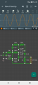
For the most recent schematic at the time of your post (this would be a lot easier with reference designators) -
220nF - This "disconnects" the shunt feedback resistor (50K) at DC. By isolating the 50K resistor, the circuit becomes a voltage follower with a gain of 1. The purpose of this is to prevent the opamp's input offset voltage error from being multiplied by the gain of the circuit. This is not a big deal with a gain of only 4, but if the circuit gain were 100, as in a microphone preamp, the shift in the output signal's DC component could cause clipping, or be a problem depending on what the circuit is driving.
2.2 uF - output coupling capacitor. In normal operation, the output sits at 4.5 V when there is no signal. A downstream amplifier might not like this.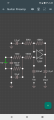
 Facebook
 Google
 GitHub
 Linkedin
 138.6 KB Views: 9
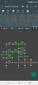 221.4 KB Views: 8