It's courteous to supply the Spec-Sheet-PDF for the Chip that You intend to use
so that others can easily look-up the Specifications of the Chip if they don't immediately know them.
Do You intend to use SMD-Components ?, or Through-Hole-Components ?
What is the ideal Input-Impedance that You would like to have ?
Is this Circuit for a Musical-Instrument, or a Home-Stereo type device ?
( are You aware of the quirks of a "Guitar-Cord" and "High-Impedance-Pick-Ups" ? )
What is the expected Output-Load-Impedance that You would like to be able to drive ?
What is the ideal High-Pass-Frequency that You would like to have ? ( Low-Frequency-Roll-Off )
What is the ideal Low-Pass-Frequency that You would like to have ? ( High-Frequency-Roll-Off )
.
.
.
I don't have any questions, I was just putting the schematic out there for anyone who would like to build it for their own use. Should I have posted the schematic on a different forum ?
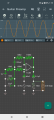
The High-End-Frequency-Response can go to the Moon with the shown-Schematic.
This can be problematic, as it means that this Circuit can amplify RF-Frequencies
and You may not be aware that its happening because it may only be audible as Distortion in the desired Frequency-range of use.
The High-Frequency-Response MUST be rolled-off for more predictable operation.
( ~10kHz would be good for an Electric-Guitar, possibly even ~8kHz, ~6kHz for Heavy-Distortion-Guitar ).
.
.
.
MANY of the folks who visit these forums are neither engineers nor simulators. Quite a few admit to being beginners. So it is a courtesy to those beginners to show the details that are presumed to be obvious by those who are well experienced.
"Equality" among all does not extend to the level of experience and training.
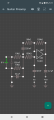
In digital logic circuit documentation, maybe; in fact, that is where the practice originated, a world where all transistors were NPN. But even there a design schematic must have some indication of what the rails are, if for no other reason than to anchor the power supply decoupling capacitors - *which your schematic does not have.* In analog circuit design it is far less common because there are no standards.
The datasheet label for the negative rail is "-Vcc". a) not GND; b) There are several things wrong with this, and it is disappointing to see TI's continual decline in the quality of their documentation. First, Vcc is a designation for a positive voltage rail. Vee is the industry standard term for a negative rail *in bipolar transistor circuits*, even those with PNP transistors. But the TL081 is a FET device. For this, the correct designations for the rails are Vdd and Vss. What does your SIM program do with that?
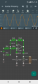
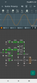
In the #1 schematic there is nothing to indicate what the IC power rails are. Does your sim program automatically assign an opamp negative rail pin to GND? If so, that is a critical design flaw.
I forgot to point out that because the shunt feedback capacitor is connected to this bias node rather than to GND, not having this node decoupled decreases the circuit gain from 4.0 (200 / 50) to 3.7 (205 / 55). You can see this in the increase in output voltage between post #7 and post #10. Note that the gain in #7 is even lower (3.55).
The design has three single-pole highpass filters built-in. Standard tuning for a 4-string bass guitar goes down to 41 Hz. For a 5- or 6-string bass it goes down to 30 Hz.
For the output of a highpass filter to be considered "flat" (less than 1 dB of output amplitude error), the corner frequency must be at least two octaves below the lowest frequency of interest. Two of the filters do not meet this. The third highpass filter is formed by the output coupling capacitor and the downstream load such as an amplifier input impedance. For any load impedance less than 9.6K, the size of the output coupling capacitor will affect the amplitude of the output signal.
Note that frequency response errors are cumulative.. Because the three filters are in series, simply adjusting them so that all corner frequencies are 7.5 Hz will not solve the problem.
 Facebook
 Google
 GitHub
 Linkedin
 122.9 KB Views: 35