New OpAmp circuit to analyse

MrAl

Joined Jun 17, 2014
13,720
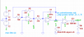
Ok, I tried to verify that what you said but I couldn't get the expected effect...
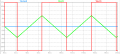
At the Output, I still have negative voltages... What is wrong here? I also stepped the wiper value to watch the Duty Cycle modulation!
View attachment 94969

Hello again,

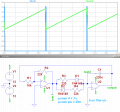
You NEED the 10k resistor from the cathode to ground.
This 10k acts like both a pullup and a pulldown resistor. It pulls DOWN the input of the next stage, and pulls UP the diode cathode.

The diode reverse leakage is very small, as the diode looks almost like a 500megohm resistor in reverse, but compared to an infinite impedance that is still enough to cause conduction. With the 10k resistor to ground, it can pull the cathode up to ground level and thus provide the required near zero output level.
Sometimes the next stage will take care of this, but if there is no next stage then it is an open circuit which is an infinite impedance and thus you could see some negative voltage.

So add the 10k and see if that clears up the negative output voltage issue (from the comparator that is).
 

Thread Starter

PsySc0rpi0n

Joined Mar 4, 2014
1,786
Hi again,

Happy to hear you got it working now. Good luck with it :)

Thanks...

I'm now running the whole circuit with the 3 Blocks... Our teacher is asking us to make the pot .25, .5 and .75. But the only value we can get some output is for the pot at .25... At .5 and .75 the OpAmp at Block 3 is saturated, therefore, the diode is preventing any output... Is there any change I can make to the circuit so that it allows me to see something else for the pot at 0.5 at least??? The 0.75 may stay as it is so that we can also show that the diode as some purpose at some point!
 

Attachments

Jony130

Joined Feb 17, 2009
5,598
Very good. So to fix this you need increase the input voltage. Do you know how you can change the triangular amplitude?
 

Thread Starter

PsySc0rpi0n

Joined Mar 4, 2014
1,786
Very good. So to fix this you need increase the input voltage. Do you know how you can change the triangular amplitude?
I think I do... According to the Schmitt Trigger working properties, the threshold voltages are set by the relationship between the feedback resistor and the input resistor times the saturation voltage (positive and negative).

So I think if I set the feedback resistor to a lower values, probably the threshold voltage will increase!
 

Thread Starter

PsySc0rpi0n

Joined Mar 4, 2014
1,786
So, you know everything, get to work on this.

Ok... This was just a side question you know! It was a curiosity question of mine. Teacher is not asking for this. But this question popped up because teacher was asking us to plot the output waveform for the pot at .25, .50 and .75. And the only value that outputs anything of interest was the .25 value so I wanted to say that the other 2 values wouldn't plot anything unless something in the circuit would change. And was this "change" I was looking for... But just to mention it and maybe let the teacher know that I went into some "investigation" to sort that out! Yes, for me is a bit of investigation because I'm a noob!
 

Thread Starter

PsySc0rpi0n

Joined Mar 4, 2014
1,786
Now, I'm analysing something else...

Check the attached pictures and the .asc file!

I'm trying to find the oscillation frequency for that circuit. Blocks 1 & 2 but with a different setup between the blocks. R+D and D+R instead of a single R as before.

I'm using the cap voltage formula to find the timings that the triangular wave takes to go from one threshold voltage to the other, but my results are not matching LTSpice simulation.

positive slope
vcap = -1/(R*C)*∫(-12-0.7)dt + V0
5.45V = -1/(22kΩ*220n)*(-12.7)t - 5.45V
t = 4.67ms

negative slope
vcap = -1/(R*C)*∫(12-0.7)dt + V0
-5.45 = -1/(220Ω*220n)*(11.3)t + 5.45V
t = 46.7us
 

Attachments

Last edited:

Jony130

Joined Feb 17, 2009
5,598
First of all in your circuit R3 is 220Ω , and this means that the capacitor charging current should be equal to:
12V/220Ω = 54.545mA. So the capacitor voltage will change in rate of 0.2479V/μs (volts per microsecond). But this charging current must be provided by Block 1 op amp. But, can he do it ?? As we can see he can not do it. Do you know why?
 

Thread Starter

PsySc0rpi0n

Joined Mar 4, 2014
1,786
No, this one I think I don't know why.

And I see you're talking about R3. Are you considering the "new" R3 with the Diode or you're yet considering yet the old single R3?
 

Thread Starter

PsySc0rpi0n

Joined Mar 4, 2014
1,786
Yes, I was talking about the "new" circuit with R3 = 220Ω and the diode.

Check your op amp model and the parameter named Ilimit.
Ok, 25mA...

After I have replied the previous post I was thinking about something we talked about in classes about a transistor that there is at the end of the OpAmp that needs a pull-up resistor to work, but probably it has nothing to do with this case!
 

Jony130

Joined Feb 17, 2009
5,598
After I have replied the previous post I was thinking about something we talked about in classes about a transistor that there is at the end of the OpAmp that needs a pull-up resistor to work, but probably it has nothing to do with this case!
Yes, you are right, the resistor want help here. Every op amp has a op amp maximum output current that he can source or sink.
And for your ideal op amp this current is 25mA. But of course you can change it or add a emitter follower.
 

Thread Starter

PsySc0rpi0n

Joined Mar 4, 2014
1,786
Yes, you are right, the resistor want help here. Every op amp has a op amp maximum output current that he can source or sink.
And for your ideal op amp this current is 25mA. But of course you can change it or add a emitter follower.
Ok, I think I'm not supposed to change the circuit. But I can ask the teacher.
About changing the parameter of the limit current, will that make my calcs match LTSpice simulation? I mean, if I change the parameter limit to, let's say, 60mA, will my calcs match LTSpice simulation?
 

Thread Starter

PsySc0rpi0n

Joined Mar 4, 2014
1,786
Change it and you will see.
I did it but still not very close to what I was expecting. But I'm not sure if the values are already acceptable or not! I mean, is the way of calculating the oscillation frequency correct or not? If it is correct, then I'll be happy because despite the values are still not very close I can explain why... I mean there are always a few reason to this difference!
 
Top