Facebook
 Google
 GitHub
 Linkedin
Ok, I want to thank you all for the insights of each one but I need to keep focus on the basics and on the academic context. I'm not sure if I'm correct, but looks like some of us here in the thread are not quite sure about what each block means. I'm not saying that you guys don't know what the blocks are, but I think this might help narrowing the options:
All already noticed this is a 3 block circuit.
The AO means only OpAmp in Portuguese, which stands for AmpOp. We use this acronym to refer to OpAmps in general without specifying if it's on amplifier mode or on comparator mode!
So, I already got the meaning of the 3 blocks.
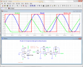
Block 1 - bistable waveform generator
Block 2 - integrator that will create a triangular waveform shape from the Block 1 coming waveform signal
Block 3 - somehow a Duty Cycle modulator/controller with Half-Wave rectification.
Tomorrow I'll get into the maths that our teacher is asking, namely, (d.)) calculate the oscillation frequency for the circuit composed by Blocks 1 & 2, (e.))draw the waveform for that circuit on key points/nodes, (f.)) then draw the waveforms when the rpot is at 1/2, 1/3 and 1/4 positions at the AO3 output and at the circuit output, meaning before and after the diode and lastly to repeat d.) and e.) replacing R3 by Block 4... I still have a lot to do!
All already noticed this is a 3 block circuit.
The AO means only OpAmp in Portuguese, which stands for AmpOp. We use this acronym to refer to OpAmps in general without specifying if it's on amplifier mode or on comparator mode!
So, I already got the meaning of the 3 blocks.
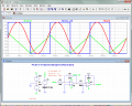
Block 1 - bistable waveform generator
Block 2 - integrator that will create a triangular waveform shape from the Block 1 coming waveform signal
Block 3 - somehow a Duty Cycle modulator/controller with Half-Wave rectification.
Tomorrow I'll get into the maths that our teacher is asking, namely, (d.)) calculate the oscillation frequency for the circuit composed by Blocks 1 & 2, (e.))draw the waveform for that circuit on key points/nodes, (f.)) then draw the waveforms when the rpot is at 1/2, 1/3 and 1/4 positions at the AO3 output and at the circuit output, meaning before and after the diode and lastly to repeat d.) and e.) replacing R3 by Block 4... I still have a lot to do!
")