Facebook
 Google
 GitHub
 Linkedin

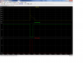
It would be nice if we knew the average voltage during the arc, but that would be difficult. That was why I decided to sample it somewhere towards the middle. If we do it the way we are talking it will start out at 113 volts and go down to 25 or so before we turn it off.. Like this picture it is not a straight line but the discharge curve of the capacitor. So my thought was to look in the middle of this waveform.Got to thinking about an analogy for the ram drive and window comparator interface. Think of it as a heavily dampened volt meter. Moves in when voltage is too high and moves out when it is too low. And stays centered when conditions are correct for sparking. The feedback loop was a poor example. Sorry.
New dumb question(got a million of them)
- Thread starter shortbus
- Start date
Scroll to continue with content

Ron, the stepper speed is again a separate control. The ram control is a well proven concept by many builders. And the transformer 'derating' is something I'm all ready doing in the main power supply. Another thing is there will be two different boards in this. One for the 'controls' and another for the caps and mosfets. And thinking maybe some opto- couplers between the comparators and the rest of the logic. To help with the electrical noise.
What you do when setting up is smear some dielectric on the top of the part and let the electrode 'touch off' on it, and set your 'zero'. It won't short if you don't let it sit there too long. This is a slow, slow process and nothing at all like drilling a hole or milling. Hard to explain and when I was learning it, after years in the die maker trade, it took a while to understand.
If you look closely at the schematic that Tony Stewart at ETO posted, the lower left corner of it shows Ananain was doing something real similar to what I'm wanting. But he was doing the control in a micro and using way higher voltages. The high voltage is something that not even the industrial machines use.
What you do when setting up is smear some dielectric on the top of the part and let the electrode 'touch off' on it, and set your 'zero'. It won't short if you don't let it sit there too long. This is a slow, slow process and nothing at all like drilling a hole or milling. Hard to explain and when I was learning it, after years in the die maker trade, it took a while to understand.
If you look closely at the schematic that Tony Stewart at ETO posted, the lower left corner of it shows Ananain was doing something real similar to what I'm wanting. But he was doing the control in a micro and using way higher voltages. The high voltage is something that not even the industrial machines use.
That graph is about perfect for a discharge. But were not using that comparator to measure the gap voltage or control the stepper. Remember the post that I asked to put the diode in series with a pot for the window comparator? Post #154 I think. The window comparator is what will control the stepper. In total there will be five comparators in the complete circuit. 1. the charged cap voltage. 2. the discharged cap voltage 3. the arc started.It would be nice if we knew the average voltage during the arc, but that would be difficult. That was why I decided to sample it somewhere towards the middle. If we do it the way we are talking it will start out at 113 volts and go down to 25 or so before we turn it off.. Like this picture it is not a straight line but the discharge curve of the capacitor. So my thought was to look in the middle of this waveform.

4 and 5. a window comparator for stepper control.
="shortbus, post: 860519, member: 61844"]
If you look at the wave form I posted (arc voltage) at the beginning it could be higher than the window and at the end it could be lower than the window. In the middle it could be just right. So the window would say to high, ok, and to low all in one arc. How will you know what to tell the stepper???
I understand it ok, but answer this question:Ron, the stepper speed is again a separate control. The ram control is a well proven concept by many builders.
If you look at the wave form I posted (arc voltage) at the beginning it could be higher than the window and at the end it could be lower than the window. In the middle it could be just right. So the window would say to high, ok, and to low all in one arc. How will you know what to tell the stepper???
How did you do this???And the transformer 'derating' is something I'm all ready doing in the main power supply.
I understand.This is a slow, slow process and nothing at all like drilling a hole or milling. Hard to explain and when I was learning it, after years in the die maker trade, it took a while to understand.
If your talking about his power supply it is not isolated and very dangerous.If you look closely at the schematic that Tony Stewart at ETO posted, the lower left corner of it shows Ananain was doing something real similar to what I'm wanting. But he was doing the control in a micro and using way higher voltages. The high voltage is something that not even the industrial machines use.
When higher than the window it moves in toward the work. Due to the lag in reaction time between stepper and voltage change the whole thing works as a 'system'. The value of the window 'null' is enough to keep it from over shooting the gap size. When in the "zone" of sparking the initial high voltage drops very fast back in to the windows 'null' or no movement area, way faster than the motor can react. When it does need to move, it only will move a step or as in my case a micro step. I say micro step because my lead screw is pretty coarse. The very first sparks of the burn/cut may cause some extra moving in and out, but once the 'zone' is established it only moves very slightly as needed.="shortbus, post: 860519, member: 61844"]
I understand it ok, but answer this question:
If you look at the wave form I posted (arc voltage) at the beginning it could be higher than the window and at the end it could be lower than the window. In the middle it could be just right. So the window would say to high, ok, and to low all in one arc. How will you know what to tell the stepper???
How did you do this???
I understand.
If your talking about his power supply it is not isolated and very dangerous.
The derating is by a large power resistor. The transformer is actually a 20Amp transformer, but only using 15 Amps.
Theoretically what I'm wanting to do could be done by a few toggle switches and a volt meter, if the machine operator, meter and switches could react fast enough. The comparators, logic and mosfets are just taking the place of the theoretical part.
 When this level/generation of edm was first done it was done using vacuum tubes. And the stepper motor was instead a 3 or 4 inch diameter hydraulic cylinder controlled with solenoid valves.
I lost track of this thread.When higher than the window it moves in toward the work. Due to the lag in reaction time between stepper and voltage change the whole thing works as a 'system'. The value of the window 'null' is enough to keep it from over shooting the gap size. When in the "zone" of sparking the initial high voltage drops very fast back in to the windows 'null' or no movement area, way faster than the motor can react. When it does need to move, it only will move a step or as in my case a micro step. I say micro step because my lead screw is pretty coarse. The very first sparks of the burn/cut may cause some extra moving in and out, but once the 'zone' is established it only moves very slightly as needed.
I think you are confusing analog and digital. Look again at the waveform for a single arc. Since we are digital with the window anytime the arc voltage is low the window will say move out because it thinks there is a short. At the beginning of the arc it will say move in because the voltage is to high making it think it is to far away. When in fact what you want is the place in the middle where it says all is well. In the example it will move out every time until it looses the arc.
There is no averaging like there would be with a volt meter or an analog servo like your hydraulics.
Good!The derating is by a large power resistor. The transformer is actually a 20Amp transformer, but only using 15 Amps.
Yes, it sounds simple until you get into the details like what to do if there is no arc and how to make it repeat, what to do with a short etc.. Then it gets more complicated.Theoretically what I'm wanting to do could be done by a few toggle switches and a volt meter, if the machine operator, meter and switches could react fast enough. The comparators, logic and mosfets are just taking the place of the theoretical part.
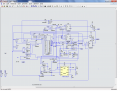
Here is a new circuit based on your idea of no "ON" timer. It simplifies things a bit.
I have one question about it though. I shut it off when the arc voltage got below the lower window threshold. The question is do you think there will ever be a case where the arc will extinguish before the voltage gets that low? I envision the high spot getting blown off and the gap being to large now for the arc to continue. I could always add "NO ARC" to reset it as well.
.[/QUOTE]
Attachments
-
 67.2 KB Views: 12
 -
 104.1 KB Views: 15
Hi Ron, thought maybe I made you upset. Again I'll print and study.
One thing that all of the homemade edm's have in common is the ram motor circuit. And they all just use a window comparator. Measuring potential between cap output and ground. Even with no arc the ram moves in until an arc starts and gets WC back in the window. When the pulse is shut off to recharge caps, the ram control see it as 'in the window' (no output) and stays in same position as when it went into off/recharge time. When next pulse starts, if it is close enough for a good spark, comparator goes right back into the window before ram can react.
Now the few pulse machines do use a small value cap (don't remember value) to keep the ram in the last position during off/ recharge time.
I think maybe your thinking the arc start comparator is controlling the ram movement?
One thing that all of the homemade edm's have in common is the ram motor circuit. And they all just use a window comparator. Measuring potential between cap output and ground. Even with no arc the ram moves in until an arc starts and gets WC back in the window. When the pulse is shut off to recharge caps, the ram control see it as 'in the window' (no output) and stays in same position as when it went into off/recharge time. When next pulse starts, if it is close enough for a good spark, comparator goes right back into the window before ram can react.
Now the few pulse machines do use a small value cap (don't remember value) to keep the ram in the last position during off/ recharge time.
I think maybe your thinking the arc start comparator is controlling the ram movement?
="shortbus, post: 863936, member: 61844"]
Because that is how this one works.
If there is no arc it moves in and tries again until it gets one the switches over to the window. The only difference is that once it detects the arc there is a short delay before it "looks" at the window. It then clocks what ever the window is saying into the flip flops at the top right to be sent to the stepper controller as an in or out command or no command at all if the voltage is in the window.
[/QUOTE]
I guess we have a failure to communicate.One thing that all of the homemade edm's have in common is the ram motor circuit. And they all just use a window comparator. Measuring potential between cap output and ground. Even with no arc the ram moves in until an arc starts and gets WC back in the window. When the pulse is shut off to recharge caps, the ram control see it as 'in the window' (no output) and stays in same position as when it went into off/recharge time. When next pulse starts, if it is close enough for a good spark, comparator goes right back into the window before ram can react.
Because that is how this one works.If there is no arc it moves in and tries again until it gets one the switches over to the window. The only difference is that once it detects the arc there is a short delay before it "looks" at the window. It then clocks what ever the window is saying into the flip flops at the top right to be sent to the stepper controller as an in or out command or no command at all if the voltage is in the window.
[/QUOTE]
The failure to communicate is due to my lack of understanding on circuits. The problem with the extended delay is the caps discharging before a 'good' discharge starts. But one skipped spark is no big deal.
Other than not having an 'or' gate between the 'and' gates and the 4013's, doesn't my simple circuit do the same thing? With no timer needed. When the 115V switches 'on' it provides a voltage to the motor window comparator, and until an arc starts the diode bias stops the discharge of the caps. Once the arc starts, the comparator below the gap shuts off the 115V. The way my pea brain sees it, it's the same as an added timer. Simple if it works is better. Unless there are other needed gates that my idea doesn't show. Like the many edge detector type delays seen in your schematic, that I don't understand.
I'm learning so much from you about how to implement things in a circuit. Stuff I now see missing in many circuits posted on line. Thank you for that and all your doing with this.
Other than not having an 'or' gate between the 'and' gates and the 4013's, doesn't my simple circuit do the same thing? With no timer needed. When the 115V switches 'on' it provides a voltage to the motor window comparator, and until an arc starts the diode bias stops the discharge of the caps. Once the arc starts, the comparator below the gap shuts off the 115V. The way my pea brain sees it, it's the same as an added timer. Simple if it works is better. Unless there are other needed gates that my idea doesn't show. Like the many edge detector type delays seen in your schematic, that I don't understand.
I'm learning so much from you about how to implement things in a circuit. Stuff I now see missing in many circuits posted on line. Thank you for that and all your doing with this.
="shortbus, post: 864191, member: 61844"]
Most of the delays are there for situations where what is called a race condition would exist without them. For example if we wanted to rese a flip flop and the counter at the same time but the counter still had to be at some value for the flip flop to be reset.
I'm learning so much from you about how to implement things in a circuit. Stuff I now see missing in many circuits posted on line. Thank you for that and all your doing with this.[/QUOTE]
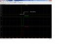
I'm not sure we are talking about the same delay. The delay before looking at the window in only a few micro seconds. Example below.The problem with the extended delay is the caps discharging before a 'good' discharge starts. But one skipped spark is no big deal.
Yes, you could do the same thing with the 4013s, but you would need 3 of them instead of just the one counter. The counter is an easy way to create sequential logic. When reset it is at zero. Then every time it gets a clock it advances by one. So it is really a bunch of flip flops in one package with a common reset and clock and a sequential output. Only one IC with one power and ground etc.Other than not having an 'or' gate between the 'and' gates and the 4013's, doesn't my simple circuit do the same thing?
I think you need a timer for another reason. Can you figure out what it is? Hint - it is when something doesn't go exactly according to plan.With no timer needed.
Yes, That is how it is designed.When the 115V switches 'on' it provides a voltage to the motor window comparator, and until an arc starts the diode bias stops the discharge of the caps. Once the arc starts, the comparator below the gap shuts off the 115V. The way my pea brain sees it, it's the same as an added timer. Simple if it works is better. Unless there are other needed gates that my idea doesn't show. Like the many edge detector type delays seen in your schematic, that I don't understand.
Most of the delays are there for situations where what is called a race condition would exist without them. For example if we wanted to rese a flip flop and the counter at the same time but the counter still had to be at some value for the flip flop to be reset.
I'm learning so much from you about how to implement things in a circuit. Stuff I now see missing in many circuits posted on line. Thank you for that and all your doing with this.[/QUOTE]
Attachments
-
 60.6 KB Views: 11
Don't know how to do the response in a quote thing that you did. So I'll put your words in quotation marks.
"I'm not sure we are talking about the same delay. The delay before looking at the window in only a few micro seconds." --- But the discharge time may only be a few uSec, depending on the cap value selected. The longest time in the whole sequence is the 'off' time, some where between 25 -100 uSec. And from where the motor window comparator is/needs to be in the circuit, waiting to send a signal isn't necessary or even desirable.
"Yes, you could do the same thing with the 4013s, but you would need 3 of them instead of just the one counter. The counter is an easy way to create sequential logic. When reset it is at zero. Then every time it gets a clock it advances by one. So it is really a bunch of flip flops in one package with a common reset and clock and a sequential output. Only one IC with one power and ground etc." --- But can a counter work in a 'state machine'? From my understanding of logic circuits, that is what this is, a state machine not sequential logic. It can't go to the next step with out completing the current step.
"I think you need a timer for another reason. Can you figure out what it is? Hint - it is when something doesn't go exactly according to plan." ---- I really can't see the need. Being a state machine if it 'stalls' it's because there is a physical problem in the gap. And the operator needs to correct it, a good thing. I guess I'm seeing this from the perspective of using one of these machines.
"Most of the delays are there for situations where what is called a race condition would exist without them. For example if we wanted to rese a flip flop and the counter at the same time but the counter still had to be at some value for the flip flop to be reset." ---- And again being a state machine a race condition can't happen. I know that state machines aren't used much any moore (little humor there), but work perfect for this application. If a value isn't met it waits until it is, no race conditions.
Ron, not trying to be difficult here. But an edm will/can work just using a RC relaxation oscillator and I may be very wrong but see this as doing the same but making it pulse.
So I'll put your words in quotation marks."I'm not sure we are talking about the same delay. The delay before looking at the window in only a few micro seconds." --- But the discharge time may only be a few uSec, depending on the cap value selected. The longest time in the whole sequence is the 'off' time, some where between 25 -100 uSec. And from where the motor window comparator is/needs to be in the circuit, waiting to send a signal isn't necessary or even desirable.
"Yes, you could do the same thing with the 4013s, but you would need 3 of them instead of just the one counter. The counter is an easy way to create sequential logic. When reset it is at zero. Then every time it gets a clock it advances by one. So it is really a bunch of flip flops in one package with a common reset and clock and a sequential output. Only one IC with one power and ground etc." --- But can a counter work in a 'state machine'? From my understanding of logic circuits, that is what this is, a state machine not sequential logic. It can't go to the next step with out completing the current step.
"I think you need a timer for another reason. Can you figure out what it is? Hint - it is when something doesn't go exactly according to plan." ---- I really can't see the need. Being a state machine if it 'stalls' it's because there is a physical problem in the gap. And the operator needs to correct it, a good thing. I guess I'm seeing this from the perspective of using one of these machines.
"Most of the delays are there for situations where what is called a race condition would exist without them. For example if we wanted to rese a flip flop and the counter at the same time but the counter still had to be at some value for the flip flop to be reset." ---- And again being a state machine a race condition can't happen. I know that state machines aren't used much any moore (little humor there), but work perfect for this application. If a value isn't met it waits until it is, no race conditions.
Ron, not trying to be difficult here. But an edm will/can work just using a RC relaxation oscillator and I may be very wrong but see this as doing the same but making it pulse.
="shortbus, post: 864660, member: 61844"]
In order to do this you need to decide when it is a delayed arc or no arc. This needs a timer.
If you have a link to a pulser with logic, please post it and we can compare.
Yes, that is true, but I think we have a spec of 25 usec. minimum and 100usec maximum. This time is easily selected by choosing the size of the cap.But the discharge time may only be a few uSec, depending on the cap value selected.
Also true. The time will be longer because of the current limiting resistor. But again easy to calculate.The longest time in the whole sequence is the 'off' time, some where between 25 -100 uSec.
I guess you will need to show me the logic for the signal you will send to the step controller. If you look carefully at the waveform above you will see the window comparator says move in, ok, and move out all in one pulse. Which will you send to the stepper. The controller spec also says the minimum pulse is 10 usec, so I think you need to remember the move command for a while.And from where the motor window comparator is/needs to be in the circuit, waiting to send a signal isn't necessary or even desirable.
yes, it can. State machine or sequential - both the same to me. I'm sure it is difficult to follow the logic but it is a state machine. For example if it at reset and gets start it will advance to charge. If charge is complete it will advance to discharge 130 if it is at discharge 130 and sees an arc it will advance to discharge etc.--- But can a counter work in a 'state machine'? From my understanding of logic circuits, that is what this is, a state machine not sequential logic. It can't go to the next step with out completing the current step.
Your quote. Even with no arc the ram moves in until an arc starts and gets WC back in the window."I think you need a timer for another reason. Can you figure out what it is? Hint - it is when something doesn't go exactly according to plan." ---- I really can't see the need. Being a state machine if it 'stalls' it's because there is a physical problem in the gap. And the operator needs to correct it, a good thing. I guess I'm seeing this from the perspective of using one of these machines.
In order to do this you need to decide when it is a delayed arc or no arc. This needs a timer.
The basic machine is pretty much a state machine, but not all."Most of the delays are there for situations where what is called a race condition would exist without them. For example if we wanted to rese a flip flop and the counter at the same time but the counter still had to be at some value for the flip flop to be reset." ---- And again being a state machine a race condition can't happen. I know that state machines aren't used much any moore (little humor there), but work perfect for this application. If a value isn't met it waits until it is, no race conditions.
Sure, they are easier, but yours is better.Ron, not trying to be difficult here. But an edm will/can work just using a RC relaxation oscillator and I may be very wrong but see this as doing the same but making it pulse.
If you have a link to a pulser with logic, please post it and we can compare.
Expand to see my answers in blue. Sorry I can't understand why your doing it like your saying. Brain isn't big enough to grasp it.="shortbus, post: 864660, member: 61844"]
Yes, that is true, but I think we have a spec of 25 usec. minimum and 100usec maximum. This time is easily selected by choosing the size of the cap. Also true. The time will be longer because of the current limiting resistor. But again easy to calculate. I guess you will need to show me the logic for the signal you will send to the step controller. If you look carefully at the waveform above you will see the window comparator says move in, ok, and move out all in one pulse. Which will you send to the stepper. The controller spec also says the minimum pulse is 10 usec, so I think you need to remember the move command for a while. That is the off time. The on time will be what it is, this is a improvement over the other way of randomly setting a time and hoping it's right. How can the window comparator give both in and out signals at the same time? One comparator is non-inverting and one is inverting. And I haven't shown that circuit yet?
yes, it can. State machine or sequential - both the same to me. I'm sure it is difficult to follow the logic but it is a state machine. For example if it at reset and gets start it will advance to charge. If charge is complete it will advance to discharge 130 if it is at discharge 130 and sees an arc it will advance to discharge etc. The 130V is not a 'cutting' voltage, just an ignition of the arc. To be shut off by the after gap detector.
Your quote. Even with no arc the ram moves in until an arc starts and gets WC back in the window.
In order to do this you need to decide when it is a delayed arc or no arc. This needs a timer.
The basic machine is pretty much a state machine, but not all. If the arc is delayed or should stop for some reason, the off timer would kick in and start the sequence over again, No waiting for any thing.
Sure, they are easier, but yours is better.
If you have a link to a pulser with logic, please post it and we can compare.
Last edited:
="shortbus, post: 864820, member: 61844"]
The window comparator can't give both signals at the same time, but it can and will give both signals in the same arc.
Look at this picture.
Yes, I understand the 130 is not the cutting voltage, but it is a part of your state machine.
But lets have a look at the pulser you have.
The window comparator can't give both signals at the same time, but it can and will give both signals in the same arc.
Look at this picture.
Yes, I understand the 130 is not the cutting voltage, but it is a part of your state machine.
Now you broke the state machine rule just as I did. You can't just say the off timer will kick in - something must tell it to kick in since the state machine is still sitting there waiting for the arc..If the arc is delayed or should stop for some reason, the off timer would kick in and start the sequence over again, No waiting for any thing.
But lets have a look at the pulser you have.
Attachments
-
 73.4 KB Views: 9
Ah, but I did think of that. When there is no output from the arc detector, there is a inverter that triggers both 'off' timer and charge mosfet back in to the start of the sequence. Or at least that's the idea.="shortbus, post: 864820, member: 61844"]
Now you broke the state machine rule just as I did. You can't just say the off timer will kick in - something must tell it to kick in since the state machine is still sitting there waiting for the arc..
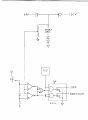
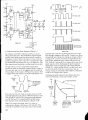
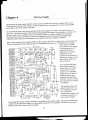
File edm 088 is the stepper logic. Except for the actual driver, just shows the conections going to driver.
File edm 089 is the Langlois book pulser circuit. But due to him not doing the highside gate drive correctly it won't work.
File edm 090 is the Fleming pulser from his book. It's the one using low side switches.
Both Langlois and Fleming use a simple PWM as there pulse time generator. Langlois using two 555 one shots alternating each other. Fleming uses the single 555 with two diferent resistors, adjust duty cycle and frequency changes.
Attachments
-
 457.1 KB Views: 19
 -
 2.2 MB Views: 22
 -
 1.7 MB Views: 18
Last edited:
Ahh, I see now.
We have been mixing features from a bunch of designs, trying to make one fancy one.
I like the 2 timer approach - very simple. What it does is just run. No state machine. It just turns on and then off for the caps to recharge.
You don't need to detect the arc since the window will move it in if there isn't one. The down side is it has no provision for a delayed arc or the 130 volt start pulse. The 130 volt might not be bad to add. The provision for the delayed arc is more difficult. but maybe not to important???
Since the frequency is always the same you can use an average for the window. It won't be quite as accurate but should work ok.
Also switching the ground side is much easier. Is there some safety reason the other one didn't do that?
We have been mixing features from a bunch of designs, trying to make one fancy one.
I like the 2 timer approach - very simple. What it does is just run. No state machine. It just turns on and then off for the caps to recharge.
You don't need to detect the arc since the window will move it in if there isn't one. The down side is it has no provision for a delayed arc or the 130 volt start pulse. The 130 volt might not be bad to add. The provision for the delayed arc is more difficult. but maybe not to important???
Since the frequency is always the same you can use an average for the window. It won't be quite as accurate but should work ok.
Also switching the ground side is much easier. Is there some safety reason the other one didn't do that?
I'll do the quote and answer thing again.
"I like the 2 timer approach - very simple. What it does is just run. No state machine. It just turns on and then off for the caps to recharge." --- But the big problem is still 'missed sparks'. And if the sparking ends due to the caps being drained of useable voltage before on time is up, the ram will start to retract. Because window voltage is low, it will seem like a short when there is none.
"You don't need to detect the arc since the window will move it in if there isn't one. The down side is it has no provision for a delayed arc or the 130 volt start pulse. The 130 volt might not be bad to add. The provision for the delayed arc is more difficult. but maybe not to important???" --- The arc detector and what I was doing with the logic, takes care of both. And keeps the circuit working if the ram is too far away to start an arc, it just waits until one starts.
"Also switching the ground side is much easier. Is there some safety reason the other one didn't do that?" ---
The second one, Fleming's, grounded the negative of his power supply to "earth". Which as a member of his internet forum, I questioned this. To me it also eliminates galvanic isolation of the whole circuit. With most of these machines being used as an attachment in a drill press or milling machine and the positive being 'hot' all the time, I see the possibility of a shock. When changing an electrode. The first one was made more to the industrial machines, with the positive side being off when not cutting. When I was running these machines it was common practice to change electrodes while the ram was going back to home position. This had the positive side still live until ram movement stopped. Got many shocks when doing this, but getting shocked doesn't bother me that much. Kind of like it.
I guess if power supply secondary side wasn't earthed, low side switching would work.
"I like the 2 timer approach - very simple. What it does is just run. No state machine. It just turns on and then off for the caps to recharge." --- But the big problem is still 'missed sparks'. And if the sparking ends due to the caps being drained of useable voltage before on time is up, the ram will start to retract. Because window voltage is low, it will seem like a short when there is none.
"You don't need to detect the arc since the window will move it in if there isn't one. The down side is it has no provision for a delayed arc or the 130 volt start pulse. The 130 volt might not be bad to add. The provision for the delayed arc is more difficult. but maybe not to important???" --- The arc detector and what I was doing with the logic, takes care of both. And keeps the circuit working if the ram is too far away to start an arc, it just waits until one starts.
"Also switching the ground side is much easier. Is there some safety reason the other one didn't do that?" ---
The second one, Fleming's, grounded the negative of his power supply to "earth". Which as a member of his internet forum, I questioned this. To me it also eliminates galvanic isolation of the whole circuit. With most of these machines being used as an attachment in a drill press or milling machine and the positive being 'hot' all the time, I see the possibility of a shock. When changing an electrode. The first one was made more to the industrial machines, with the positive side being off when not cutting. When I was running these machines it was common practice to change electrodes while the ram was going back to home position. This had the positive side still live until ram movement stopped. Got many shocks when doing this, but getting shocked doesn't bother me that much. Kind of like it.
I guess if power supply secondary side wasn't earthed, low side switching would work.

Some car accessory shops used to sell a spark voltage gauge for testing ignition HT.Wanting to measure the voltage going through a spark gap. Measuring it on the input side only tells me that, the input. Even if the spark isn't jumping the gap, it will show the voltage feeding the gap, not useful for my project.
I did a lot of reading, and found a college thesis showing how the author did it. Will it work doing it this way? Putting a diode of the proper voltage and amperage value between ground electrode and actual ground, the measuring at junction of diode and ground electrode. Thesis claims it gives gap voltage one diode drop above ground, what do you think?
Sorry but forum won't let me upload my schematic?
Sort of plastic pair of dividers with spark gap contacts mounted on each arm, on the pivot was like a protractor and a pointer that indicated the voltage reading.