New dumb question(got a million of them)

ronv

Joined Nov 12, 2008
3,770
="shortbus, post: 865339, member: 61844"]
From #196-Ah, but I did think of that. When there is no output from the arc detector, there is a inverter that triggers both 'off' timer and charge mosfet back in to the start of the sequence. Or at least that's the idea
Yes, that would work, but you need to decide how long to wait before you decide there has not been an arc. That needs a timer.

But the big problem is still 'missed sparks'. And if the sparking ends due to the caps being drained of useable voltage before on time is up, the ram will start to retract. Because window voltage is low, it will seem like a short when there is none.
Yes, I think you are right. For example if you chose a small cap and a long on time. That brings us back around to needing to sample the arc someplace in the middle like in post 196. Did you study that one?

"You don't need to detect the arc since the window will move it in if there isn't one. The down side is it has no provision for a delayed arc or the 130 volt start pulse. The 130 volt might not be bad to add. The provision for the delayed arc is more difficult. but maybe not to important???" --- The arc detector and what I was doing with the logic, takes care of both. And keeps the circuit working if the ram is too far away to start an arc, it just waits until one starts.
This can work with the second circuit I posted since the on timer is quite long or it the first circuit that reset the adjustable on timer if there is a delayed arc. And yes the arc detector can be used to turn off the 130.

"Also switching the ground side is much easier. Is there some safety reason the other one didn't do that?" ---
The second one, Fleming's, grounded the negative of his power supply to "earth". Which as a member of his internet forum, I questioned this. To me it also eliminates galvanic isolation of the whole circuit. With most of these machines being used as an attachment in a drill press or milling machine and the positive being 'hot' all the time, I see the possibility of a shock. When changing an electrode. The first one was made more to the industrial machines, with the positive side being off when not cutting. When I was running these machines it was common practice to change electrodes while the ram was going back to home position. This had the positive side still live until ram movement stopped. Got many shocks when doing this, but getting shocked doesn't bother me that much. Kind of like it.:)

I guess if power supply secondary side wasn't earthed, low side switching would work.
Probably better safe than sorry.[/QUOTE]

Maybe I'll take a look at some combination of the 2 timer that does not adjust the on time but relies on what cap is selected.
 

ian field

Joined Oct 27, 2012
6,536
Thanks Ian, but this is not 'high' voltage really. Only around maximum(and only for a few uSec) of 130Vdc. Then it drops back to the around 40Vdc range. And the detection is only to trigger some logic.
Neons usually have a specific breakdown voltage in the range about 70 - 90V. They can give a one shot (flash) indication or used to trigger a circuit. For lower voltage increments, diacs like the DB3 break down at about 32V. Any combination can be strung in series and fed to the gate of an SCR.
 

Thread Starter

shortbus

Joined Sep 30, 2009
10,049
Ian, your getting into this thread kind of late, and a lot has been already answered. The detection also needs to stay on during the total discharge time. Ronv was using a neon bulb in his LTspice circuits to take the place of a spark gap, since a spark gap is hard to simulate. The idea of two diodes in series with the gap and ground was in a circuit I had found. And he has been kind enough to help me even farther with this project. A lot of good reading and information (at least for me) if you want to start at the beginning. Don't mean these comments as derogatory, just that a lot has already been explained. Feel free to join in after seeing what has already been done.
 
Last edited:

Thread Starter

shortbus

Joined Sep 30, 2009
10,049
Doing the copy and quote again.

"Yes, that would work, but you need to decide how long to wait before you decide there has not been an arc. That needs a timer." ---- Why? With the boost voltage, the only reason for no arc would be the fluid in the gap. And since it is under a slight pressure, it will take care of it's self. And the inverter on the detector won't do anything until after the detector has gone high and changed a flip flop. Self timer:)

"Yes, I think you are right. For example if you chose a small cap and a long on time. That brings us back around to needing to sample the arc someplace in the middle like in post 196. Did you study that one?" --- Which file in post 196? I've studied those files so much, and this circuit of mine is what I came up with.

"This can work with the second circuit I posted since the on timer is quite long or it the first circuit that reset the adjustable on timer if there is a delayed arc. And yes the arc detector can be used to turn off the 130." --- I still don't get the reason for all the extra logic and timer.

"Maybe I'll take a look at some combination of the 2 timer that does not adjust the on time but relies on what cap is selected." --- Using the arc detector does that with no timer.

Is there a reason why what I came up with shouldn't work? I did a simple simulation of the flip flop/and gates/or gate on something called Logsim and it looked workable.
 

ronv

Joined Nov 12, 2008
3,770
="shortbus, post: 865736, member: 61844"]

"Yes, that would work, but you need to decide how long to wait before you decide there has not been an arc. That needs a timer." ---- Why? With the boost voltage, the only reason for no arc would be the fluid in the gap. And since it is under a slight pressure, it will take care of it's self. And the inverter on the detector won't do anything until after the detector has gone high and changed a flip flop. Self timer:)
I think there will be a lot of times when there will be no arc. Not so many with the boost voltage but still a lot of times. Don't forget even it is only a once in a million problem it will happen every couple of minutes.

"Yes, I think you are right. For example if you chose a small cap and a long on time. That brings us back around to needing to sample the arc someplace in the middle like in post 196. Did you study that one?" --- Which file in post 196? I've studied those files so much, and this circuit of mine is what I came up with.
The waveform attached to post 196.

"This can work with the second circuit I posted since the on timer is quite long or it the first circuit that reset the adjustable on timer if there is a delayed arc. And yes the arc detector can be used to turn off the 130." --- I still don't get the reason for all the extra logic and timer.

"Maybe I'll take a look at some combination of the 2 timer that does not adjust the on time but relies on what cap is selected." --- Using the arc detector does that with no timer.
It is the missed arc that requires a timer.

Is there a reason why what I came up with shouldn't work? I did a simple simulation of the flip flop/and gates/or gate on something called Logsim and it looked workable.
Add your changes to that one and I'll give a shot a simulating it. Maybe you could add the part that moves the motor at the same time.
Tell me how long the timer is in your circuit and add something to turn it off.
 

Thread Starter

shortbus

Joined Sep 30, 2009
10,049
copy and quote again.

"I think there will be a lot of times when there will be no arc. Not so many with the boost voltage but still a lot of times. Don't forget even it is only a once in a million problem it will happen every couple of minutes." --- I can live with every couple of minutes.:) In the other machines being built it is sometimes every couple of on times, many times a minute.

"The waveform attached to post 196." ---- Do you mean file #edm090? My file? Or are we talking about your wave form in post #195?

"It is the missed arc that requires a timer." --- The way I see it, with the voltage still high (missed spark) the ram will advance until it contacts the work piece, effectively a short with no arc. This will cause the ram to retract and allow debris to get washed out of gap. And cycle starts over again, due to inverter on the detector resetting off timer. This random retraction is something that some industrial machines use, to improve gap conditions.

"Add your changes to that one and I'll give a shot a simulating it. Maybe you could add the part that moves the motor at the same time.
Tell me how long the timer is in your circuit and add something to turn it off." --- I've been struggling with "DipTrace" to draw my circuits better and will try doing it there. May take a day or so though. The timer is a one shot, a 4538, set as a non-retriggerable. So it turns it's self off. I'll add the time range in the circuit though, since it needs to be adjustable.

Thanks for sticking with me through this!!
 

ian field

Joined Oct 27, 2012
6,536
Ian, your getting into this thread kind of late, and a lot has been already answered. The detection also needs to stay on during the total discharge time. .
Tie the bottom of the neon to the gate of a SCR and it does stay on - or at least the SCR does.
 

ronv

Joined Nov 12, 2008
3,770
="shortbus, post: 865927, member: 61844"]
Do you mean file #edm090? My file? Or are we talking about your wave form in post #195?
Yes, sorry my 195.

Anyway the 3rd time is the charm or last, but not least, etc.

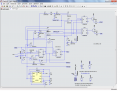
Here is about as simple as we're going to get..

It is based on a single timer that is free running. During the positive output of the timer the caps are charged and during the negative portion the discharge cycle takes place.
It is not totally a state machine, but oh well. Most of it is the same as the others except the on time is set by which caps the operator selects. The larger the cap the longer the time. The discharge is turned off if the cap voltage goes below the "short" or low window or if for some reason the arc is lost.
The maximum time it waits for an arc is about 200 usec. So that means a 100 usec arc could be delayed by 100 usec and things would be normal.
The time allowed to recharge the caps is about 400 usec and the same time is used for the motor step.
Before you build it we should probably built a little timer just to drive your motor to make sure it has enough torque at 2500 steps per second to move the ram down.
Once we know that we can optimize the speed based on the cap charge rate, the power supply max current and the motor maximum step rate.
Attached is a 'normal waveform and the schematic. I was going to describe the function of each IC, but it might be better if you look at it and ask questions.
 

Attachments

Thread Starter

shortbus

Joined Sep 30, 2009
10,049
Printed it and will study. One thing right off the bat that's troubling is the "2500 steps per second" for the motor driver. That's really moving! 750RPM! 1 or 2 steps per second would be more like it.

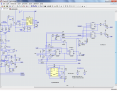
Here is my schematic you asked for. Didn't put in voltage dividers to scale the voltages for comparators. Hope it makes sense.
 

Attachments

ronv

Joined Nov 12, 2008
3,770
Printed it and will study. One thing right off the bat that's troubling is the "2500 steps per second" for the motor driver. That's really moving! 750RPM! 1 or 2 steps per second would be more like it.

Here is my schematic you asked for. Didn't put in voltage dividers to scale the voltages for comparators. Hope it makes sense.
I think they are getting similar.

I didn't mean to imply that there would be many steps except perhaps when first starting, But the steps - lets say two in a row would happen at a 2500 step per second rate (400 usec apart). The motor has to respond to these two steps.
 

Thread Starter

shortbus

Joined Sep 30, 2009
10,049
I think the difference is I'm seeing it as a mechanical thing done by electronics/logic. And your approaching it from more of a micro controller aspect. :)

When still working I had this type argument all the time with engineering. On a machine with many 'stations' they were concerned with "parts per minute"(PPM) so they programed to move from station to station on a 'average' of the time all stations took. Some times a slight mechanical delay would happen but the line would move while a station was still doing it's job. Machine breakage and down time to repair was often the result of that. But the engineers didn't care about that because it didn't show up on the PPM, so they looked good. If limit switches had been added to the machines at each station to signal that it's job had been done, the PPM would not have suffered much but the overall good parts per shift would have gone way up. Due to less down time for repairs.

That is the basics of what I've tried to do in my schematic. The comparators are acting as 'limit switches'. Won't let one 'station' to advance until the last one is completed. Instead of clock driven. :)

There's a way around the need for speed on the step driver I haven't shown. When advancing the ram or retracting it before or after a burn, there will be a switch for cutting and manual. In manual the speed can be dialed up and then be lowered for cutting. The ram won't move from it's home position under control of the logic. I'll scan the part of the Langlois circuit that I'm using for that and post it. The step timer is in the upper left corner.
 

Attachments

ronv

Joined Nov 12, 2008
3,770
I think the difference is I'm seeing it as a mechanical thing done by electronics/logic. And your approaching it from more of a micro controller aspect. :)

When still working I had this type argument all the time with engineering. On a machine with many 'stations' they were concerned with "parts per minute"(PPM) so they programed to move from station to station on a 'average' of the time all stations took. Some times a slight mechanical delay would happen but the line would move while a station was still doing it's job. Machine breakage and down time to repair was often the result of that. But the engineers didn't care about that because it didn't show up on the PPM, so they looked good. If limit switches had been added to the machines at each station to signal that it's job had been done, the PPM would not have suffered much but the overall good parts per shift would have gone way up. Due to less down time for repairs.

That is the basics of what I've tried to do in my schematic. The comparators are acting as 'limit switches'. Won't let one 'station' to advance until the last one is completed. Instead of clock driven. :)

There's a way around the need for speed on the step driver I haven't shown. When advancing the ram or retracting it before or after a burn, there will be a switch for cutting and manual. In manual the speed can be dialed up and then be lowered for cutting. The ram won't move from it's home position under control of the logic. I'll scan the part of the Langlois circuit that I'm using for that and post it. The step timer is in the upper left corner.
I don't think that circuit works unless there is something else on another page. As a matter of fact it is worse than that. The timer is just running. It has no relationship to the pulse. So whenever it clocks the window comparator that's what it will tell the motor to do. It could happen anytime.
No, I am trying to protect against those little glitches that break the line. Maybe that's why it is a bit more complicated than the others you find on the internet that don't seem to work to well.
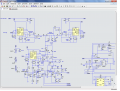
Anyway, having said that here is the one similar to yours that uses only a single timer. The only option it doesn't have it the provision for a delayed arc. If the arc is delayed it will just be shorter. The pot on the timer sets the burn time.
I have now simulated the entire circuit together so if it's ok with you I think I will post it in a separate thread to see what kind of feedback I get.
 

Attachments

Thread Starter

shortbus

Joined Sep 30, 2009
10,049
I don't think that circuit works unless there is something else on another page. As a matter of fact it is worse than that. The timer is just running. It has no relationship to the pulse. So whenever it clocks the window comparator that's what it will tell the motor to do. It could happen anytime.
No, I am trying to protect against those little glitches that break the line. Maybe that's why it is a bit more complicated than the others you find on the internet that don't seem to work to well.
Anyway, having said that here is the one similar to yours that uses only a single timer. The only option it doesn't have it the provision for a delayed arc. If the arc is delayed it will just be shorter. The pot on the timer sets the burn time.
I have now simulated the entire circuit together so if it's ok with you I think I will post it in a separate thread to see what kind of feedback I get.
There is nothing on another page. But there is something on that page that doesn't belong, the motor window comparator circuit. The motor window comparator and its pulse generator and logic is a separate circuit unto itself. I just added it because you asked.

I think we still have a misunderstanding. The motor drive is only connected to the power pulse circuit by the reading of the voltage on the positive gap line. Other than that, what is going on with regard to the logic controlling the power/cutting pulses have no linkage. The motor drive circuit just monitors the gap and moves as appropriate. Using the power pulse circuit to clock the motor is not what is needed.

The off timer in my circuit is just that, a one shot, triggered when the gap detector goes low. When it times out (goes high) it powers up the 90V and 20V comparators again, then shuts down until the gap goes low the next time. By using it to shut down the comparators monitoring the cap bank, this prohibits the circuit from advancing until the cap bank conditions are correct. Due to the slow amount of time that it takes to remove the metal when burning, the power circuit may go through many cycles before the need to move comes up. Even hundreds or more cycles, depending on the size of the electrode.

In regards to a delayed arc, the motor circuit will see a high voltage and move in. If it still doesn't arc it will move until it 'shorts' and move out. This is desirable, since if an arc doesn't start it means there is too much debris in the gap, so it should retract to allow the debris to flush out. The "short and backout" should give a high then a low on the arc detector, this will then cycle the one shot and take everything back to the starting point of the cycle of pulses- the charging of the cap bank.

I'm sorry I have such a hard time of conveying the way these machines work. But it is really step by step, with the steps being controlled by voltage in each area.

I have no objection to posting your circuit in a separate thread. Thank you again for your help with this.
 
Top