No, I think we are all on the same page with that.
It is just that with a working gap of only .001 inch even with 1/4 steps you are only 5 or 6 steps away from the part. So we need to be careful we only give 1 step for each move in that is required.
Cmartinez, you mentioned programing and using a micro for this. I have no experience with a micro, but with the talk of others trying to build DIY edm machines that have tried using them, it's not the programing that is the bottle neck, it's RF and electrical noise that edm makes that is the problem. Even using optocoupling doesn't get around it. But using the old TTL CD4xxx logic doesn't seem to have as much problem.
I hadn't thought of that... yes, you're going to be generating your own small lightning storm in a bucket, and your machine's going to become one powerful broadcaster at wide frequencies. In that area I'm almost completely useless as an adviser (but that only makes me get more interested in this subject ).
Anyway, if you decide to go the way of an MCU just let me know and I'll be more than happy to help. In fact, I suggest you design it in a way that the controller PCB card can be easily changed, and with easy to find and replace connectors and other hardware. That way you could try different approaches for controlling the thing.
I hadn't thought of that... yes, you're going to be generating your own small lightning storm in a bucket, and your machine's going to become one powerful broadcaster at wide frequencies.
I don't see this as insurmountable it is done in the industrial field all the time.
PC based/logic controllers with CNC Plasma etc, just to name a few.
I have found that the 'noise' problem is generally because of poor decoupling, grounding and bonding of systems.
I am tied up with a pressing project right now or I might be tempted to look into something for this application.
Max.
I don't see this as insurmountable it is done in the industrial field all the time.
PC based/logic controllers with CNC Plasma etc, just to name a few.
I have found that the 'noise' problem is generally because of poor decoupling, grounding and bonding of systems.
I am tied up with a pressing project right now or I might be tempted to look into something for this application.
Max.
You're right... I've worked with Plasma machines too and they're far noisier than anything I've seen (what could be noisier, btw?)
Anyway, I guess it all comes down to proper shielding as you say.
Shortbus, I fail to see why a dedicated circuit would be more robust than an MCU, but of course, it's your call. Just make sure that the final circuit leaves you with enough flexibility, working range and i/o's to automate the process as much as possible. Either way, I'll be here to help, if I can.
The video in #131 is from an industrial machine and is more stable then the DIY ones or ones from the generation of machines I'm trying to build. I wanted to show ones from a Langlois build but can't find one yet, a guy named Jim Glass had two of them years ago on the net, one a sinker and the other a wire.
I did find two built from the Fleming books one a RC machine and the other a pulse machine. Both use a Maxon gearhead motor @80RPM, much faster movement than a stepper.
This one is the RC machine, near the end of it it shows the motor rotating. It isn't a smooth burn but it is because the motor moves so fast it overshoots the 'window' and has to back up. No problem like this when using a stepper. But the widow controller circuit it similar to Langlois.
This one is the pulse machine, but the same Maxon motor drive. Same overshoot problem but window circuit is even closer version of Langlois circuit, this was due to my fighting them on Fleming's forum.
Watch the volt and amp meters in this one, the open circuit voltage drops fast, faster than the stepper circuit would react.
Could you post a picture of your big resistors? I want to see how they are wound, I'm hoping they are non-inductive type, and maybe we can tell with a picture.
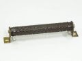
Ron, don't have a digital camera, but here is one from the web that is the same style I have. Ohmite corrib, with the corrugated flat ribbon element. The caps are Rifa PHE 450 - 2pcs 4.7uF, 4pcs 3.3uF, 2pcs 2.2uf, 14pcs 1.5uF and a few 1.0uF
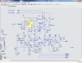
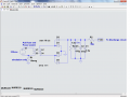
This is the discharge circuit with the windows.
The window is about 5 volts wide and adjustable up and down with a center from about 25 to 45 volts.
Short is at 18 volts.
I'm still not sure of the shape of the pulse, but from reading it doesn't sound like anyone fully understands it, so we may need to play with the cap sizes and resistor sizes.
I'm going to do the 2 power supplies next, so be thinking about anything you want in the logic before we get there.
Thank you Ron!! I have to print these out and study them to figure out what's happening in them, not enough knowledge to just do it with a glance. I have a question about U6 and it's output called +short, what is it and what is it doing? Usually 'short' and 'move out' are the same thing, at least for the motor control. Thank you again.
Thank you Ron!! I have to print these out and study them to figure out what's happening in them, not enough knowledge to just do it with a glance. I have a question about U6 and it's output called +short, what is it and what is it doing? Usually 'short' and 'move out' are the same thing, at least for the motor control. Thank you again.
Hey, our first cost reduction! I thought the low end and the short were very close together. I'll modify it tomorrow. It is pretty busy.
The arc detect I think you understand. It just looks for voltage across the big diodes and sends a signal to the logic to turn off the 130 volt supply and start the timer for the burn.
Move in and move out are from the window to tell the logic where to go. The center of the window is adjustable with the potentiometer.
The rest is pretty much the same as the other circuits in that it is just a high speed switch.
There is quite a bit of "stuff" to protect from the high voltages from the arc.
Thanks for the answer Ron. Now not to doubt you, but can I ask why the window circuit is done the way it is? Form my limited knowledge of electronics and window comparator circuits, I thought the voltage you were comparing/measuring was to be the same on both comparators. One voltage scaled down in this case to a working level the comparators can use. And the 'reference voltages' for the comparators were two separate values. Just the opposite of your schematic.
I've been going to dialysis training with my wife all week so haven't had time to look for my old notes/schematics of the way I figured it out a few years ago. Put them where I wouldn't forget where they were, and forgot. Old age and strokes are hell. Again not to doubt you on this just wondering why, I can never thank you enough for the help your giving me!!
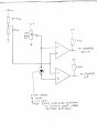
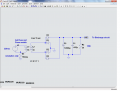
Didn't find my old all of my old edm notes yet. Way too many hobbies and projects going on. But redrew the basics of it, without putting in values of resistors. Don't want to go down that path until either I find the old or you say it won't work my way. Have a look and see what you think. May need a resistor from the Schottky diode to ground to forward bias it at the correct voltage for a 5V window gap.
"Edit" Found the schematic of this idea. Who in the world would put it in a file drawer?
Didn't find my old all of my old edm notes yet. Way too many hobbies and projects going on. But redrew the basics of it, without putting in values of resistors. Don't want to go down that path until either I find the old or you say it won't work my way. Have a look and see what you think. May need a resistor from the Schottky diode to ground to forward bias it at the correct voltage for a 5V window gap.
"Edit" Found the schematic of this idea. Who in the world would put it in a file drawer?
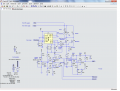
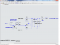
Looks good to me. Here is an update. Window from 20-26 and 40 to 46 on the high end.
Ron, the numbers look great! So my idea wasn't too far off base after all? I finally feel like I'm contributing to my own thread. Again, thank you for all your hard work!
Ron, the numbers look great! So my idea wasn't too far off base after all? I finally feel like I'm contributing to my own thread. Again, thank you for all your hard work!
Wow Ron, your a glutton for punishment, huh? For indicators volt and amp meters would be great. I'll need to think some on logic to make sure I'm getting it correct. One small but probably inconsequential thing is the 130v, in reality it will be 113v dc.
I'll really be interested in how the 12v 'isolated supply' is implemented for the gate drives. This is another thing that people told me wouldn't work for gate drives, that you have to use a bootstrap circuit. This was a few years ago when I started out.
Wow Ron, your a glutton for punishment, huh? For indicators volt and amp meters would be great. I'll need to think some on logic to make sure I'm getting it correct. One small but probably inconsequential thing is the 130v, in reality it will be 113v dc.
Not a problem. But I'm not sure an ammeter is a good idea. I hate to put anything in the high current path that doesn't have to be there. Let me think about it a bit.
I'll really be interested in how the 12v 'isolated supply' is implemented for the gate drives. This is another thing that people told me wouldn't work for gate drives, that you have to use a bootstrap circuit. This was a few years ago when I started out.
Maybe they meant a charge pump. I don't think a bootstrap circuit would work here. For bootstrap to work there needs to be a path to ground while the FET is off to charge up the bootstrap capacitor. The little supplies just add 12 volts where the bootstrap would normally go. They have to be isolated because the (-) side does not go to ground but rides on top of the high voltage.
Here is one.
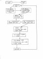
Ron, as you asked for here is a block diagram of the logic. The amp meter is not a big deal, but a volt meter would be nice. It would show the gap conditions. Thank you again for all the help.
Don't know why my logic diagram shows as a broken link now, will try again.
What would really be great would be a second comparator on the cap bank that would take the place of the "discharge/arc on timer". That would start the "charge/ arc off" timer when it went below a set low voltage, but an arc on timer will be fine.

 Facebook
 Google
 GitHub
 Linkedin




 ).
).