negative voltage rails

Thread Starter

Homebrew1964

Joined Nov 22, 2024
281
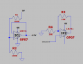
I have built the circuit, the sinewave input from my function generator goes directly into pin 3 of IC2 it is 0.5V above and below ground (1V pk to pk total), my output is only showing the top half of the waveform as expected and i believe i have to supply IC2 with split supply, how do i do that? where do i connect pin 4 of IC2 to please?
 

Attachments

sghioto

Joined Dec 31, 2017
8,709
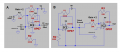
Don't need a split supply if using capacitors on the input and output on version A. Max output appx 7Vp-p at 9 volt supply.
Version B produces a "virtual ground" for the signal input and output eliminating the capacitors on IC2. Output appx 7Vp-p at 9 volt supply

1783820978597.png
 
Last edited:

dl324

Joined Mar 30, 2015
18,425
how do i do that?
Use 2 9V batteries. Connect them in series and define the connection between them to be GND. Connect GND from the signal generator to the node you've defined as GND.

I suggest 2 9V batteries because LM741 is severely limited with supplies below that. The input and output ranges are only guaranteed to be withing 3V of the rails.
 
Certainly to get an actual negetive voltage as part of a waveform, you must have an actual negative supply voltage to that stage. There are work-around schemes to provide an equivalent output, mostly involving capacitor coupling.
 

Thread Starter

Homebrew1964

Joined Nov 22, 2024
281
Use 2 9V batteries. Connect them in series and define the connection between them to be GND. Connect GND from the signal generator to the node you've defined as GND.

I suggest 2 9V batteries because LM741 is severely limited with supplies below that. The input and output ranges are only guaranteed to be withing 3V of the rails.
I'm using a bench power supply set to 9V
 

WBahn

Joined Mar 31, 2012
32,999
Don't need a split supply if using capacitors on the input and output on version A. Max output appx 7Vp-p at 9 volt supply.
Version B produces a "virtual ground" for the signal input and output eliminating the capacitors on IC2. Output appx 7Vp-p at 9 volt supply

View attachment 369402
While the output is TYPICALLY 7 Vpp on a 9 V supply, if it only turns out to be 3 Vpp, there's no room to complain because it is still operating within spec.
 

WBahn

Joined Mar 31, 2012
32,999
Circuit B works beautifully. i expected a gain of 1 though since R3/R4 = 1 ?
Why do you expect that?

You need to spend the time and effort to understand how the basic op-amp circuits behave, which means being able to analyze their expected behavior and not just throw equations around without knowing whether or not they apply to the given circuit.
 

MisterBill2

Joined Jan 23, 2018
27,809
Consider that SOME opamps are intended for single supply operation. That is , the LM324 type, at least. Of course, that means no negative voltages in the application. So there isalways a compromise involved.
 

MrChips

Joined Oct 2, 2009
34,970
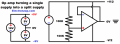
Whether a supply rail is positive or negative is irrelevant. The polarity is relative to a reference node.
The solution is to create a reference node that is at the midpoint of the supply voltage. We call this node "COMMON" or PSEUDO GROUND or VIRTUAL GROUND.

We connect all 0-volt references to this COMMON node.

1783864399333.png
 

dl324

Joined Mar 30, 2015
18,425
Circuit B works beautifully.
It works for a 1V peak to peak input signal, but the guaranteed input/output voltage swing is only guaranteed to be 3V peak to peak with a +/-4.5V supply. That's why I suggested using 2 9V batteries.
1783866290106.png
1783866304281.png
1783866352541.png
1783867494864.png
For heavily loaded outputs, it's not guaranteed to work.

LM741 was designed in an era where opamps usually operated from +/-15V supplies.

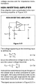
i expected a gain of 1 though since R3/R4 = 1 ?
This is how the gain formulas were derived (from Signetics Analog Applications Manual) using the zero differential input theorem:
1783866506930.png 1783866529135.png

1783866563902.png
 
Last edited:

WBahn

Joined Mar 31, 2012
32,999
That's true with a 1K load but appx 6Vp-p at 10K as measured in testing.
The 3 V from the rail comes from the spec with a 10 kΩ load. With a 2 kΩ load, it's only guaranteed to get within 5 V of the rail, meaning that it might now work at all.

Also, note that this is with ±15 V rails. With ±4.5 V rails the swing might be different, but probably not by a lot.

You will likely get upwards of 7 Vpp swing, as that is the typical case. But relying on the part you happen to have being typical is not sound practice.
 
Top