I know I'm not as smart as the rest of you, and have said this before, but is the speed tach wire from the motor connected? Go to your data sheet and read page #4 the part called "pulse blocking". Most of these vary speed routers use the pid type part of the circuit. To prevent stalling the motor at slower speeds. If it isn't getting the tach signal the circuit shuts down. You can tell if this is being used in your router by seeing if pins 16 and 18 are connected together by a trace on the PCB.
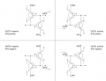
Shortbus, I have looked into the tach wire scenario and here is what I know. There are two pink wires that go into the field housing. There are two white wires that come out of the field housing and go the brushes. there are two short white wires that look like they go between the coils. I can see nothing of any tach sensor anywhere or any wires coming from the housing that look like they would be from anything but the field coils. As for pin 16 & 18, if you look at my hand drawn diagram in Post #29, they do not connect together directly but do connect to a SMD capacitor C155. That would make sense to me to have a tach sensor, but so far, I see nothing.
If you look at my diagram though, where is it picking up the signal. I see nothing inside the motor that looks like a tach sensor of any kind. If I power this motor directly, it will run all day. Where is the signal coming from?
If bwilliams wasn't the first to take the router apart, the speed control wire could possibly be missing. From the data sheet it looks like you can disable that part of the circuit by jumpering pins 16 and 18. But that would also do away with the current control when the router is slowed down.
It's hard to do this 'long distance'. The speed sensor may not be a component that is visible, it could be in the windings. I'd look for a broken wire around the motor windings. Or a place that a wire was, on both the motor and control board.
I'm not the first one to have the unit apart but I don't see where anything has been disturbed. The owner of the router said he took it apart, ran it without the speed control to see if the motor worked, and then put it back together. I don't believe he is capable of anything electrical and I really cannot see where anything has been changed. This is very puzzling.
Okay I measured the voltage across terminals 2 and 3 and I wasn't sure if you meant AC or DC (assumed DC) but here they are:
AC voltage - Startup 5.44 VAC Running 0.26 VAC Stopped 0.14 VAC
DC Voltage - Startup 15.98 VDC Running - Same Stopped 16.10 VDC
I'm thinking that is better than what I had the first time I tried this.
Good call R!f@@. I went over the board again and found the one under the TRIAC damaged but still measuring okay (looks like the side blew out of it) and then I found another one (Red,red, orange, gold - 22K) that measured 90 ohms. I think this may be what was missing as it goes indirectly back to pin 8? You can see it in my post #29 in the diagram, labelled as 22K. What are your thoughts? Now I am worried about the TRIAC. Is there a way to test a TRIAC. I have seen a 12V circuit on the Internet using a 12V 6W lamp. Is this a viable method. I don't think it can be done with a multimeter. Thoughts?
Replaced the blown resistor.
Remove the 22K one and check out of circuit for proper resistance.
Then give me a reading of the triac gate and MT1. Which are the side pins. This reading is what I check to see if the triac is OK or not. The reading should be taken by a DVM in diode check mode.
Basically these readings between gate and MT1 varies. I have seen readings as low as 0.061V which I believe is faulty. Good reading can be from 0.2V to 0.4V. I have a few triacs right now and checked them for ur convenience. The bad ones I replaced shows 0.05V to 0.07V and new ones gives me different values say from 0.15V to 0.4V depending on the part no.
I am trying to find a 22K-1/2W resistor. Still searching my stock. As for the TRIAC, I may be SOL as far as what I have here.
Original TRIAC measures 0.068 both ways on diode test
Replaced TRIAC measures 0.030 both ways
New TRIAC measures 0.030 both ways. I have not used this one yet
Not sure what to think but my own logic would say one on board and new one are okay. What are your thoughts? I don't have much experience with TRIACS.
Refer to the primitive model of a triac. A diode like junction from the gate to the output (MT2). No continuity from MT1 to MT2 unless you activate the gate with, at maximum, 50 ma. Find a voltage supply, a resistance that will allow about 50 ma, and a load. You can reverse polarity to check the "other" way.
Thank you #12. Correct me if I am wrong. Can I use a circuit with 24 ohms at 12 volts to achieve this? I seen a circuit using 12V and a 6W bulb. Just for curiosity, how did you come about 50mA?
 Facebook
 Google
 GitHub
 Linkedin
")