Need Help with Triac and Phase Control Unit Not Working

Thread Starter

bwilliams60

Joined Nov 18, 2012
1,442
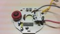
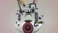
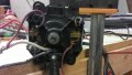
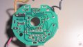
Okay here is what's new. This is a woodworking router and I found a blown capacitor on the board. It was a 1.5 uF SMD capacitor. If I bypass the speed control, the router works with no problem. With the speed control, nothing. I have checked most of the components that I can with my meter and I am now down to what I think is a TRIAC problem or the actual phase control IC (U211B). At this point, I may be a little over my head. Not sure how line voltage can be controlled on such a small board to run a motor. Can someone enlighten me in laymans terms how this works and perhaps some guidance on further diagnostics. I have hand drawn the entire board and it looks very similar to the attachment. the only difference I see that is major is that my line voltage (L) is connected to the TRIAC and my neutral is connected to my motor. Don't think it matters but... Anyways,most of the rest of the circuit has minor variations in numbering but seems to be pretty much the same. Thanks in advance.
Forgot to mention. Capacitor has been replaced.
 

Attachments

Last edited:

shortbus

Joined Sep 30, 2009
10,045
Is the speed sensor in the motor giving a signal to pin #8? If that (speed sensor) isn't giving feed back to the chip, prtty sure it shuts the speed control down.
 

Thread Starter

bwilliams60

Joined Nov 18, 2012
1,442
What type of signal would I be looking for and what will I use to measure it. I guess if you tell me what type of signal it is, the second question will come to light.
 

Thread Starter

bwilliams60

Joined Nov 18, 2012
1,442
Sorry Max, I wasn't geting any response on the other one because it started out as capacitor identification thread and morphed into TRIAC/Phase control problem. Is there a way to blend the two together. I would have rather cut the old one off and starter this one new. I thought the other one was dead.
 

shortbus

Joined Sep 30, 2009
10,045
What type of signal would I be looking for and what will I use to measure it. I guess if you tell me what type of signal it is, the second question will come to light.
Not sure what "type" of signal the chip is expecting, probablly a pulsing square wave of unknown voltage. But the schematics in the PDF show a signal coming from the motor. To tell the control how fast the motor is turning, not sure but think this type of control is called PID. Without this feed back to the control chip it would be in "open loop", and when a load is put on the motor the speed would go down. With the feed back it tries to maintain the speed it's set at. Kind of like 'cruise control' for a car.

That said I'm not knowledgeable enough to tell you what the signal should look like. It may come from a hall sensor, or an optical sensor, or ... If either one, maybe wood dust is keeping it from sending the signal. Or a broken wire. Either way, it looks like the control chip expects/needs this to work, looking at the example schematics in the chip PDF.
 

Thread Starter

bwilliams60

Joined Nov 18, 2012
1,442
I replaced the TRIAC in the board and replaced the bad capacitor, cleaned up all the wiring and put it back together. It still does nothing. I checked the voltage at the TRIAC and there is line voltage on the gate, and line voltage on A1. Any ideas. If I am correct, I need some sort of signal voltage from A2, is that correct? Will it also be AC voltage or DC voltage. I do not see a rectifier so I would assume AC. Any help is good.
Here is the TRIAC datasheet. BTA24-600BW
http://www.st.com/web/en/resource/technical/document/datasheet/CD00002264.pdf
 

MaxHeadRoom

Joined Jul 18, 2013
28,700
Like i believe i posted in the other thread, if you reverse engineer the half dozen components in there and post it, we can most likey put you in the right direction!.
Max.
 

Thread Starter

bwilliams60

Joined Nov 18, 2012
1,442
Okay, I have reverse engineered a drawing and I believe it to be correct so I will add it here as an attachment and see what we can figure out. Most of the small units are SMD and anything not labelled is because there was no labelling on it. Not 100% sure how to identify SMD caps yet but they are brown in color about 3/16" wide by 1/4" long (give or take). Not sure on the speed control as I got variable readings placing my leads all three ways ranging from 0.2 ohms to 33 K ohms.
 

Attachments

R!f@@

Joined Apr 2, 2009
9,918
Your diagram is confusing to me.

The IC pin no. 17 connection is not connected how it is specified in the IC's data sheet.
Am I missing something here ?
 

Thread Starter

bwilliams60

Joined Nov 18, 2012
1,442
R!f@@, you would be half correct. The fault is actually mine in the way I numbered the chip. #17 is actually across from #2. #18 across from #1, #16 across from #3 and so on. My apologies. Still looking for any answers or any help on this one. Little confused on where my problem lies.
 

R!f@@

Joined Apr 2, 2009
9,918
oooooooooooK Lemme see.
Here is what I would do. Do what I ask and post.
1. Check the AC Voltage between Neutral (or Pin 2 ) and Pin 7 of the IC.
2. Check the DC voltage between Neutral ( or Pin 2 ) and Pin 3 of the IC. ~ This would be a negative DC reading

A Digital Voltmeter is preferred but if you have an Analog one ( to measure the voltage at second measurement ) you need to use the Positive probe on pin 2 and negative probe on pin 3. This will cause the needle to go up. Use the probe normally and the needle will slam on to zero limit of the meter.

If you cannot measure voltages I cannot help much you know.

Warning
Mind you that this circuit is always LIVE. Be careful.
You are dealing with mains voltage and measuring across IC pins is tricky business. One slip and you might BLOW a few components.
An Isolation transformer is advised if you not familiar with measuring AC mains circuits.
Atleast this way you will be safe from Mains Voltage.

PS.. can you correct your circuit (the pin numbering) and post it. Looking at data and your circuit and keeping in mind the PIN mishap is rather u know confusing :confused:
 

R!f@@

Joined Apr 2, 2009
9,918
By the way.
Looking at your confusing diagram...Two components connect to Pin 18 of IC ( to ur right ) is not correct.
The labelled ones "104" & "100nK100" ....is completely useless according to the drawing.
I suggest you recheck the reverse engineering skills. ;)
 

Thread Starter

bwilliams60

Joined Nov 18, 2012
1,442
I did as you asked and here is what I can tell you and a couple things I don't understand so perhaps you can shed some light.
1) The voltage measured between pins 2 and 7 (red lead on pin 2) is 0.514VAC
2) The voltage measured between pins 2 and 3 (red lead on pin 2) is 1.62 VDC
Question 1 - In the U211B diagram, it shows the line to be directly connected to the motor and neutral to the TRIAC through R8. When I look at my motor, the black wire coming in goes to the switch, through the switch, out the yellow wire which is connected to the PCB to the two junction wires. My white lead which I consider to be neutral is connected to the motor. This is backwards in my world. Am I reading something wrong. Obviously if I switch my wiring, I get a negative DCV as you stated

I have corrected my diagram, thank you for picking up on the mistakes. It has been a while since I reverse engineered a PCB. I am a Motive Power Professor and deal mostly with DC electrical so I am quite familiar with components and measuring instruments so feel free to talk to me in lingo. If I don't understand, I will tell you and I am okay working with mains voltage. Have found myself on my ass on more than one occasion :)
 

Attachments

R!f@@

Joined Apr 2, 2009
9,918
Have found myself on my ass on more than one occasion :)
You and me both.

Okay...
Voltage at pin 3 is not good according to datasheet I think. It should be around 13V but I am not sure yet.
Pin 7 wrong...I made a typo:(. What I wanted to write was Pin 17 (not 7)
Sorry about that :). I will leave my above post as it is.
Can you recheck point 1...Check VAC between pin 2 & 17.
 

R!f@@

Joined Apr 2, 2009
9,918
One more thing..
Can you post some pics of the PCB from both sides. Good clear pics.
And I like to see how the motor is connected.

By the way did you try replacing the IC
 

R!f@@

Joined Apr 2, 2009
9,918
The Component you labelled "Cap?" is not a cap according to datasheet.
It should be a diode.
The component between 6.5K R to pin3 of IC should be a diode providing the negative voltage stated in datasheet.
Is this the blown component ?

If that component was blown u need to replace the IC I believe.
If not then I like to know what component is blown from the diagram.
 

Thread Starter

bwilliams60

Joined Nov 18, 2012
1,442
Attached are some pics I took of this unit. As per your directions I measured pin 2-17 and found 1.2 vac. The IC has not been replaced at this point. Only replaced Triac and C155 smd cap located just right of center and just below the center of the diagram i made. It was blown open. As for the part I marked as cap?, I believe you are correct that it is a diode. Forward biased measures 0.542 and reverse measures OL.
 

Attachments

R!f@@

Joined Apr 2, 2009
9,918
Then is it possible to measure all the high value resistors.
It is possible a resistor to be open.

I will need some time to go thru your images.
If you bare patience I can solve the issue.
 
Top