Need Help with Triac and Phase Control Unit Not Working

Thread Starter

bwilliams60

Joined Nov 18, 2012
1,442
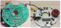
I have all kinds of patience. I won't be near the circuit board until later this afternoon. I can test whatever you need at that time. Thank you for your help
 

R!f@@

Joined Apr 2, 2009
9,918
From your pictures it seems the blown component was not a capacitor but the diode.
Am I right?
But I am having doubts if it were a diode. The part of the blown component tells me it was cap.
Do not power up the circuit yet.

I need to study it further.
 

Thread Starter

bwilliams60

Joined Nov 18, 2012
1,442
If you look at the picture, it would be the black cap labelled 155 at about the 2:00 position in relation to the hole. It originally looked like the yellow one located at about 7:00 in the picture. It was definitely a cap. The original picture is also included there showing the bad component before replacement. Pictures 5 & 6 (before and after)
 

R!f@@

Joined Apr 2, 2009
9,918
Yup !
It is a cap.
So is the diode that provide -Vs OK and also the resistor that is connected to it ?

Can you please check for dead short in all the electrolytic capacitors. Discharge all of em before testing
The tantalum one too
 
Last edited:

Lestraveled

Joined May 19, 2014
1,946
Hi bwilliams
Could you do an ohms check of the triac that you pulled out? Set your meter on the "diode" setting on the ohms scale, if it has it. Otherwise, use the 2K scale. Mainly interested in the reading between the gate (G) and the other two terminals (A1,A2). You may have to reverse the polarity of the leads to get a reading.
 

Thread Starter

bwilliams60

Joined Nov 18, 2012
1,442
Yup !
It is a cap.
So is the diode that provide -Vs OK and also the resistor that is connected to it ?

Can you please check for dead short in all the electrolytic capacitors. Discharge all of em before testing
The tantalum one too
Is the first paragraph a question or a statement? If I read you right, you are referring to the diode with the number 3 on it? It checks out okay (0.544 and O.L.) and the resistor checked out okay at 6,460 ohms. I measured from pin 3 to pin2 and got roughly 3.45 M ohms if I remember correctly. Not exactly sure what you are after. To check my caps, am I just looking for a reading of o.oo ohms across each capacitor. I think I may actually have a capacitor checker here but can I check them right on the board?
 

R!f@@

Joined Apr 2, 2009
9,918
I am trying to rule out shorted caps as tantalum and electrolytic do get short from time to time.
If the caps are correct you will get a high or open ohms reading after a few secs as the caps get charged during testing. Or you can test with cap tester and confirm there are no bad caps.

By the way I think there is only one diode on the PCB, right ?
 

Thread Starter

bwilliams60

Joined Nov 18, 2012
1,442
Okay I checked the old TRIAC and here is what I got. Red lead placed on first letter - Black lead on second. Diode test first, ohms test second
G - A2 = O.L. O.L.
G - A1 = 0.068 71 ohms
A2 - A1 = O.L. 37 M ohms
A2 - G = O.L. 37 M ohms
A1 - A2 = O.L. O.L.
A1 - G = 0.068 71 ohms

I am still working on caps and resistors. Apparently I have to go do some Christmas shopping now. Get back to this in a bit. :)
 

Lestraveled

Joined May 19, 2014
1,946
bwilliams
A normal meter that is set on the "diode" setting, should display junction voltage. For silicon semiconductors that should be from .50 to .70 volts. When you measured between G and A1 you got .068 volts. So, this indicates that the triac has a gate to A1 short. So, it looks like replacing the triac was a good thing. So, why is it not working??

I am betting that one of the 22uf caps are shorted.

R!f@@ is doing an excellent job assisting you.
 

Thread Starter

bwilliams60

Joined Nov 18, 2012
1,442
He has been doing well by me and I hope ha and yourself stay on this thread and see it through. I appreciate all the help and teachings as I go through this. Thank you for your assistance on the TRIAC. I wish I knew more about them and I am sure it will come in time but for now, I need all the help I can get.
 

R!f@@

Joined Apr 2, 2009
9,918
Hmmm. Triac giving a rather low reading. ??

If you have he function in the meter do the test in Diode range.
The triac you have as I see can be checked this way in the diode range.
The middle pin should not show any Vf to the adjacent pins in any polarity.

The only reading you should get is from the adjacent pins only. reading from either polarity should be same and in the diode range it will be around 0.1V to .24V. I get around these from the triacs I have. Any voltage below 0.1V seems bad or leaky gate

By the way polarized caps should be tested with proper polarity. Never connect in reverse.
 

R!f@@

Joined Apr 2, 2009
9,918
OP , I need to know the color coding of the marked resistors from the picture attached.
Check the resistance and post the results

Second thing I like to know is under the component replaced. The track running under the component...how is the track? Intact or burned due to the cap blowing.

Third is the PCB the triac is mounted. Is it just a blank PCB or are there any components mounted with the triac ?
 

Attachments

Thread Starter

bwilliams60

Joined Nov 18, 2012
1,442
1) The resistor colors are as follows along with the measured value.
1/2 watt on diagonal is Blue-Green-Red-Gold (6,5K +/-5%) measures 6,760 ohms
1/4 watt with it is Orange-White-Yellow-Gold (390K +/- 5%) measures 379,000 ohms
1/4 watt with it is Orange-White-Yellow-Gold (390K +/- 5%) measures 379,000 ohms (TRIAC)
1/2 watt by speed control is Red-Red-Orange-Gold (22K +/- 5%) measures 89 ohms
2) Track underneath blown capacitor was nice and clean - no problems found
3) The TRIAC is mounted on the PCB with a Black block behind it. Not sure of its purpose. Back of Triac rivets to the shield which covers circuit board. A resistor comes off the center pin (A2?) and pink lead comes off center pin and goes to motor area
TRIAC test results are in post #50 with diode test first, followed by resistance test .
4) Electrolytics seem to test fine
5) Some SMD resistors did not test as numbered but I figure because they are in the circuit
6) 100nK100 tested at 1.5 uF.
 
Last edited:

shortbus

Joined Sep 30, 2009
10,045
Since the motor is good(without speed control) and mos of the board components are good, have you checked the speed pot for opens?
 

Thread Starter

bwilliams60

Joined Nov 18, 2012
1,442
Yes I checked it and found three different readings which kind of threw me off. I was looking for a fixed resistance between two pins and found that all three readings were variable between 0.2 - 33,000 ohms roughly.
 

Lestraveled

Joined May 19, 2014
1,946
What is the AC voltage across pin 2 and 3 of the IC? (Before you checked the DC voltage at these points, now measure the AC voltage.)
What is the AC voltage across the 6.5K resistor?

Again, be very careful making these measurements. No bare feet, plan how to place your probes with the power off. Think, and then think again, before doing. Take it easy on that fine Canadian beer while doing this.
 

Thread Starter

bwilliams60

Joined Nov 18, 2012
1,442
I will check it out tomorrow and get back to you. You are funny guy but remember, our beer doesn't have as much water in it :) I'm good with checking AC mains voltages. I've learned a few lessons over the years, without alcohol I might add and they have stuck with me. I've learned from Hydro guys, left hand in back pocket and I wear rubber soul slippers on carpeted floor :) Anyways, I will be back tomorrow afternoon with some results.
 

Thread Starter

bwilliams60

Joined Nov 18, 2012
1,442
I checked out the voltages (black lead on white wire-neutral) and found only 0.8 VAC across pins 2 and 3. Across the 6.5 K ohm resistor, I dropped 69.3VAC.
Here is where I am confused. If I follow the voltage back to pin 2, I have to go through the SMD diode. But this would be reverse biased in my world. Sorry I work in conventional theory all day. So my way of thinking is that current has to come from pin 2 and pass back through the resistor to neutral.
As I said earlier, my diagram and the U211B datasheet i provided are backwards when it comes to "L" and "N". I take them to be Line and Neutral which to me means Black and White (wiring). If that is the case, it is backwards from my diagram. The black wire however, has a flag spade terminal on it and goes to the switch.
Across the TRIAC now, I only have Line voltage on the T2(A2) terminal and 0.00 on both the gate and T1(A1) terminals. Totally confused now.
 
Last edited:
Top