That is correct. I went over it again last night and i don't see where I made any mistakes. I think at this point, the only thing I can do is try another IC and if that doesn't work, I think I am going to make a frisbee out of the circuit board.
That is correct. I went over it again last night and i don't see where I made any mistakes. I think at this point, the only thing I can do is try another IC and if that doesn't work, I think I am going to make a frisbee out of the circuit board.
Just a comment from my son. "why do we have all of these dimmer switches, we leave them all on high anyhow".
Also, if you want a decent dimmer circuit for a 500 W halogen, go to a garage sale and buy an old Halogen torchier lamp that everyone had in the 1990s. They worked pretty well. At least pull them model numbers from the triac and check the gate voltages and capacitors used in those as a start.
Not sure I am quite following but if you are suggesting to check the gate voltage at the TRIAC, I guess I did that by checking pin 4 of the IC and it was 0.85 VAC and dropped out to zero when the router quits. In DC, it was even lower but I am not sure if it is AC or DC. I am assuming it should be AC but I am not well versed on this as of yet. Are you saying my IC is failing or something else might be failing?
I would have thought that with all the expertise here, someone would have been able to help me figure it out. I just put a second new IC in and the same result. I guess I am on my own. Thank you for the help. Cheers!
OK...here is what I would do.
Since the resistors are checked, hoping you have checked the surface mount resistors too.
I would take out the electrolytic caps and check them with a capacitance meter.
Next I would check the SMD caps for short circuits.
I think you have soldered the replaced cap the wrong way.
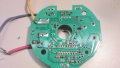
I went thru it for a long time and from the looks of it the negative of the replace 155 SMD cap should be the other way.
Just to be sure measure the cap DC voltage to check polarity.
If you reverse connected it, you need to a new one.
I see what you are saying. In post #11 of this thread, you can see the original cap before I removed it.
I guess we should stick to one thread. Can we do that. I will stay on this thread.
Footnote: I had to guess at the value of this cap and went from the leftover piece of it and the existing one on the board. Not even sure if it is the right one nor how to figure out what it should be.
Okay I will put a new one in the opposite way and see what happens. May not hear back from me tonight but first thing in the am. Not sure if my clock jives with forum clock but it is 4:34 pm here. How can I check my clock?
Thank you for your help today. I see from other posts that you stay very busy on here so I thank you for your time. Same to DodgyDave.
155 cap is wrong from diagrams.
It should be a 220nF or a 2.2μF both around 10VDC cap.
Try a 220nF first, these does not have a Polarity.
But from the color of it I'd say a 2.2μF 10V. This has polarity.
Orient band side to the other side this time
Either way what you soldered is soldered the wrong way. This I am like almost sure.
Can I use a full size electrolytic cap just to try it out. I don't have that sizei tantalum SMD and will have to order. In the meantime I would like to see if it helps our cause?
 Facebook
 Google
 GitHub
 Linkedin