Need Help with fairly simple circuit to control servo

Thread Starter

knbpixels

Joined Aug 10, 2016
12
Hi all, thanks for the help in advance. I am a novice when it comes to this stuff. This project is going into a car to control a servo that will turn 90 degrees clockwise and back.

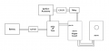
Design considerations:

Servo controlled by https://www.sparkfun.com/products/13118
Relay used as switch for controller, relay triggered by power from ignition accessory circuit in car
Servo starts in position A when relay switch is open
Servo moves to position B upon key on (ignition accessory)
Servo moves back to position A upon key off (done automatically by controller)

It is important for the controller to not drain the battery if possible, I'm not sure how best to accomplish this...I'm thinking maybe a Delay off timer? If that will work, the sequence should be: Key off, delay timer starts countdown, servo moves to position A, delay timer kills the circuit.

One thing I have a question on, is doesn't that mean the delay timer will get power 24/7...and if so, are there delay off timers that that do not draw power after they have counted down? I would appreciate any recommendations for a timer that would work.

I have attached a schematic, drawn to the best of my ability and knowledge. Appreciate input and telling me where I'm going wrong!
 

Attachments

dendad

Joined Feb 20, 2016
4,451
I would use an Arduino Nano to do it all. That will be cheaper than the Sparkfun board too, and more adjustable.
And, as for drawing a small current when off, that is not a worry as the car battery has quite a large capacity and modern cars have already current drawn when off, and a few more mA will not be a problem.
If you have not used Arduinos before, this would be a good project to learn with.
 

Thread Starter

knbpixels

Joined Aug 10, 2016
12
I would use an Arduino Nano to do it all. That will be cheaper than the Sparkfun board too, and more adjustable.
And, as for drawing a small current when off, that is not a worry as the car battery has quite a large capacity and modern cars have already current drawn when off, and a few more mA will not be a problem.
If you have not used Arduinos before, this would be a good project to learn with.

Thanks that's an interesting idea I will look into...as little electronics experience I have, it's even less so with programming.

Regarding current draw, it's more of an issue for me than most because this is a classic project car that may be only driven once a week...but perhaps thats plenty to keep an arduino running without killing the battery?
 

dendad

Joined Feb 20, 2016
4,451
I am confused by your explanation a bit.
It sounds to me like you just want to operate something when the ignition is on, then release it when the ignition is off.
A solenoid with a spring return could do that.
What are you actually trying to do? It is often a lot easier to help when a full understanding of the project is there.
 

LowQCab

Joined Nov 6, 2012
4,025
Your picture looks like You have a Regulator of some sort connected directly to the Battery.
If this is a Switching-Regulator that's not good,
a Switching-Regulator may pull an unacceptable amount of Current at Idle.
A linear-Regulator would probably be OK though.

Why don't You just tell us what You are trying to accomplish ???
.
.
.
 

Thread Starter

knbpixels

Joined Aug 10, 2016
12
I am confused by your explanation a bit.
It sounds to me like you just want to operate something when the ignition is on, then release it when the ignition is off.
A solenoid with a spring return could do that.
What are you actually trying to do? It is often a lot easier to help when a full understanding of the project is there.
So basically I will have a shallow mount touchscreen stereo in my dashboard, and I want the ability to hide it. I will 3d print all of the bracketry for it. I will have a panel attached to the top of the stereo that matches my dashboard. When the car is off the panel is presented. When the car is turned on, the servo turns and rotates the stereo 90 degrees from horizontal to vertical, to show the stereo and hide the panel. So in essence the panel and stereo are one L shaped object to rotate back and forth based on the state of the ignition accessory power.

If the sparkfun servo trigger won't draw much current when the relay is open and the servo is in the A position, then maybe the delay off timer isn't needed?
 

Thread Starter

knbpixels

Joined Aug 10, 2016
12
Your picture looks like You have a Regulator of some sort connected directly to the Battery.
If this is a Switching-Regulator that's not good,
a Switching-Regulator may pull an unacceptable amount of Current at Idle.
A linear-Regulator would probably be OK though.

Why don't You just tell us what You are trying to accomplish ???
.
.
.
The servo will reveal and hide a stereo in the car...turn the car on, servo reveals the stereo. Turn the car off, servo hides the stereo. I was concerned about current draw when sitting in the garage as the car will be sitting for a week at a time, possibly 2 weeks depending on the circumstances
 

Thread Starter

knbpixels

Joined Aug 10, 2016
12
Your picture looks like You have a Regulator of some sort connected directly to the Battery.
If this is a Switching-Regulator that's not good,
a Switching-Regulator may pull an unacceptable amount of Current at Idle.
A linear-Regulator would probably be OK though.

Why don't You just tell us what You are trying to accomplish ???
.
.
.
As far as the regulator goes, I was looking at something like this for the 12v to 5v step down: https://www.amazon.com/Converter-DROK-Voltage-Regulator-Waterproof/dp/B07P663XJV
 

dendad

Joined Feb 20, 2016
4,451
To save "off" power, as you have a mechanical device there, when power is applied via ignition on the controller (whatever you go with) drives the bracket, and in the operated position, the bracket closes a switch the holds power on.
Then, when the ignition is off, power is held on by the bracket operated switch until it moves back to the home position. Much like the homing switch on wind screen wipers.
The ignition power feed is via a suitable rated diode so it will not back feed the ignition.
 

LowQCab

Joined Nov 6, 2012
4,025
OK good,
now, why do You need a "Servo-Trigger-Board", and what does it do.
This appears to be a really complex way to go about doing this.
~3-Standard Automotive "Cube-Relays" and 2-Limit-Switches should be all You need,
unless your Actuator has a "Stepper-Motor", which would be huge over-kill.

It's super easy to make the whole contraption just turn it's self Off when it's done.
.
.
.
 

Thread Starter

knbpixels

Joined Aug 10, 2016
12
OK good,
now, why do You need a "Servo-Trigger-Board", and what does it do.
This appears to be a really complex way to go about doing this.
~3-Standard Automotive "Cube-Relays" and 2-Limit-Switches should be all You need,
unless your Actuator has a "Stepper-Motor", which would be huge over-kill.

It's super easy to make the whole contraption just turn it's self Off when it's done.
.
.
.
Valid response for sure, I was hoping to reduce mechanical complexity, perhaps at the expense of circuit complexity...Also I couldn't wrap my head around:

When the limit switch is contacted and the bracket if held against it keeping it off, how do you then apply power to the motor to turn since the circuit is killed by that limit switch. And how do you trigger the motor to turn when ignition is turned off? Use a normally closed relay?

Lastly, a large part of why I went that route was that it allowed me to use a servo and controller and not have to worry about motor speed (adjustable), and final position (adjustable). If I use limit switches I have to make sure I make the bracketry dead on, or risk having to reprint it until I get it right
 

dendad

Joined Feb 20, 2016
4,451
And it all could be done with just a DPDT relay to reverse a motor, and normally closed limit switches at the end of the travel to stop the motor.
These switches are operated by the frame at the end of the travel in that direction.
Each limit switch will need a reverse diode across it to allow the motor to run the other direction when the power polarity reverses.
DashDisplayFlipper.png
I think this is about correct.
When the ignition is on, the relay operates and applies power to the motor via the Limit Open switch, gnd via the diode across the Limit Closed switch, and the motor runs until the Limit Open switch hits the end stop.
When the ignition is off, the relay releases and applies power to the motor via the Limit Closed switch, gnd via the diode across the Limit Open switch, and the motor runs until the Limit Closed switch hits the end stop.
This method would be more in keeping with a classic car as it is just electro-mechanical.
Oh, add a fuse too.

EDIT: I missed the above postings while writing this :(
 

Thread Starter

knbpixels

Joined Aug 10, 2016
12
And it all could be done with just a DPDT relay to reverse a motor, and normally closed limit switches at the end of the travel to stop the motor.
These switches are operated by the frame at the end of the travel in that direction.
Each limit switch will need a reverse diode across it to allow the motor to run the other direction when the power polarity reverses.
View attachment 243524
I think this is about correct.
When the ignition is on, the relay operates and applies power to the motor via the Limit Open switch, gnd via the diode across the Limit Closed switch, and the motor runs until the Limit Open switch hits the end stop.
When the ignition is off, the relay releases and applies power to the motor via the Limit Closed switch, gnd via the diode across the Limit Open switch, and the motor runs until the Limit Closed switch hits the end stop.
This method would be more in keeping with a classic car as it is just electro-mechanical.
Oh, add a fuse too.
I appreciate drawing out the electro-mechanical approach for me, I will definately consider it. I'm still leaning towards the original approach as it allows me to fine tune the servo speed and A/B positions.

Any advice apart from rethinking the overall method? I'm thinking maybe the servo controller won't draw enough power to matter and I won't need the delay off timer.
 

dendad

Joined Feb 20, 2016
4,451
the servo controller won't draw enough power to matter and I won't need the delay off timer
An Arduino can operate a power switching relay to allow all power but the Arduino's own to be removed. And the Arduino will just draw a few mA when at rest.
EDIT: I think I will go back to bed now. It is early morning here. I'll look to see what you decide later.
 

Thread Starter

knbpixels

Joined Aug 10, 2016
12
In checking the current draw of the servo controller I found its only 5 mA, which from what I understand you want to stay under around 60mA to not drain a car battery between uses. I don't expect there will be any other sources of drainage happening, so I'm comfortable with that, which means I can avoid the delay off timer circuit. I also realized I don't need a step down converter for the relay, just for the board, since the relay is just closing and not passing power. Updated drawing attached. It's hard to imagine a setup being more simple than this, honestly. The servo controller will move the servo to position A on ignition, and return it automatically on power off. and the controller being $17 compares just fine to an arduino, without the complication of programming. Of course I will dedicate a fuse to this as well. Thanks for helping me think this through. I welcome any other thoughts though.
 

Attachments

DNA Robotics

Joined Jun 13, 2014
647
A lot of radios have a wire or 2 that operate a power antenna.
It lowers the antenna after you turn the car off.
Maybe you can use that circuit if your radio has it.
 
Top