Facebook
 Google
 GitHub
 Linkedin

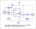
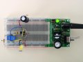
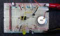
Attached is a photo of a breadboard using a 555. It is not your circuit, but it shows how to place the capacitors. C3 is a .1uF cap that goes from pin 1 to pin 8 of the 555; there is no polarity, so it can go in either way. C4 is a 10uF cap that is across the power bus; it is polarized and the negative side of the capacitor must go to the ground and the positive side must go to +VDC.
Notice that, electrically, the two caps are in the same exact place in the circuit, i.e., from ground to +VDC, but physically, they are in different locations on the breadboard. That is because they perform two different functions. C3 is to protect the 555 from noise on the power bus. C4 is to suppress the noise that the 555 puts onto the power bus. It is not absolutely required that they be arranged this way, but it is most important that C3 be physically very close to pins 1 and 8 of the 555.
Notice that, electrically, the two caps are in the same exact place in the circuit, i.e., from ground to +VDC, but physically, they are in different locations on the breadboard. That is because they perform two different functions. C3 is to protect the 555 from noise on the power bus. C4 is to suppress the noise that the 555 puts onto the power bus. It is not absolutely required that they be arranged this way, but it is most important that C3 be physically very close to pins 1 and 8 of the 555.
Attachments
-
 109.8 KB Views: 18