Need help to light up 8 LEDs with different color

tracecom

Joined Apr 16, 2010
3,944
Bernard,

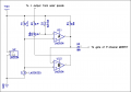
Here is the comparator schematic with the solar panel and regulators added. Note that I have used a pair of BS250 MOSFETs because that's what I have. In addition, I have added R6 to function as a pull-up for the MOSFET gates.

I think that this schematic plus the NE555N/LED schematic attached to post #239 is the entire circuit. I still need to add the values for the LED current limiting resistors.

Please advise of any corrections or additions. Thanks.

I have put both schematics together, but that means that some of the component number designations changed to avoid duplicate numbers. That file is attached as a PDF.

ETA: Removed R6 and deleted the PDF.
 

Attachments

Last edited:

Bernard

Joined Aug 7, 2008
5,784
Verry nice. Might be better to keep the two drawings separate for numberings sake. I see that the gate is well pulled up, R4 & R6 are almost in parallel. If this all works , we need to add battery charging & this will require another B/B as with SP loaded its output will be too low to charge a 12V battery directly. Ahhaaa- more comparators, FETs, & gates.
 

Thread Starter

jenovauh

Joined Jul 4, 2013
246
Hi Tracecom, thank you so much for the nice and clear drawing. I can fully understand how the circuit work now. :)

Hi Bernard, thank you so much for all the time and ideals to design this circuit, is there anything else needed to be add in or modified before I can construct them? Also does this circuit meet the requirement for pulsing the LEDs at 720Hz or higher?
 

Bernard

Joined Aug 7, 2008
5,784
Good morning all. The ckt. as drawn by tracecom should do what you wanted, jenovauh. We will need another B-B for SP charging of battery & another LM393 for control & low battery cut off. Will try to figure it out this week.
 

Thread Starter

jenovauh

Joined Jul 4, 2013
246
I have extra Buck Boost and LM393, so that's not an issue. But I don't have BS250, can replace with IRLZ44N or FDS9435A? I have quite a lot of FDS9435A, it is good to use that and also for the connection, will there be much changes on the existing layout?
 

tracecom

Joined Apr 16, 2010
3,944
I have extra Buck Boost and LM393, so that's not an issue. But I don't have BS250, can replace with IRLZ44N or FDS9435A? I have quite a lot of FDS9435A, it is good to use that and also for the connection, will there be much changes on the existing layout?
The FDS9435A will be fine. I think that Bernard will be adding some circuitry to what we already have, so the existing layout won't change much, but there will be some additions.
 

Thread Starter

jenovauh

Joined Jul 4, 2013
246
Using the one piece of FDS9435A can replace the two pieces of BS250 right? FDS9435A have 4 Drain pin, 3 Source pin and 1 Gate pin. Can I just connect the 2 Drain, 2 Source and 1 Gate pin base on the schematic layout of BS250?
 

tracecom

Joined Apr 16, 2010
3,944
Using the one piece of FDS9435A can replace the two pieces of BS250 right? FDS9435A have 4 Drain pin, 3 Source pin and 1 Gate pin. Can I just connect the 2 Drain, 2 Source and 1 Gate pin base on the schematic layout of BS250?
The four drain pins are connected together inside the MOSFET; likewise, the three source pins are connected together inside the MOSFET. You can connect to only one pin for the source, one pin for the drain, and one pin for the gate. Or, you can connect to all four of the drain pins, all three of the source pins, and the one gate pin. Electrically, it doesn't matter. Only one FDS9435A is required.
 

Bernard

Joined Aug 7, 2008
5,784
jenovauh, does the SOP to DIP8 plug into a breadboard? Normally the multiple common pins can carry more current, but at 200 to 300 mA, one pin for each function should be OK.
tracecom, all reference numbers that I use will be from your deleted post, I made me a copy.
 

Bernard

Joined Aug 7, 2008
5,784
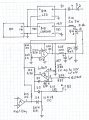
Barring any senior moments, this should be final attimpt. I'll hold off attempt at explanations untill tracecom can work his majic so that all labling is consistant. I connot breadboard as I'm missing critical components.
 

Attachments

tracecom

Joined Apr 16, 2010
3,944
Barring any senior moments, this should be final attimpt. I'll hold off attempt at explanations untill tracecom can work his majic so that all labling is consistant. I connot breadboard as I'm missing critical components.
Hey, you are the magician; I am only the scribe. :)

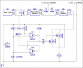
Anyway, here's my attempt at incorporating the charging circuit. I used all the component designations exactly as you drew them in the attachment to post 256. After the connections are verified, I'll check all the component designations for redundancy and consecutiveness.

The only change I made was in the Vcc pin for U4, from 5 to 8.

Also note that I still don't know the resistance values for the LED current limiting LEDs.

Let me know what corrections and improvements you want.

Is the ground side of each of the boost-buck and buck regulators common between the input and output?
 

Attachments

Last edited:

Thread Starter

jenovauh

Joined Jul 4, 2013
246
Hi tracecom, the LED current limiting resistors are 95 ohms. And thanks both the magician for the wonderful design and artwork.

I do not have resistor that are 2W rating. I can series a few 1/4W to make up the 2W rating right?
 

tracecom

Joined Apr 16, 2010
3,944
Hi tracecom, the LED current limiting resistors are 95 ohms. And thanks both the magician for the wonderful design and artwork.

I do not have resistor that are 2W rating. I can series a few 1/4W to make up the 2W rating right?
95 ohms is not a standard value; are you using 91 ohms or 100 ohms or what?

No, to increase the power rating, you put them in parallel. You would need eight 1/4 watt resistors, each 40 ohms, but 39 ohms would be close enough.

Better wait for Bernard to check the new schematic before you start soldering.
 
Last edited:

Thread Starter

jenovauh

Joined Jul 4, 2013
246
Okay noted, I have quite a lot of 39 ohms to do the job then. I think I might have some 1/2 W value. Will google what is the value to put in parallel to form 5 ohms 2W.
 
Top