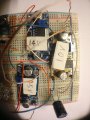
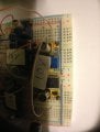
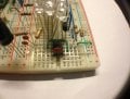
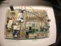
Finally finished the assembling but it is not working. double check and triple check still dont understand what is wrong. Anyway all the variable resistors value should not affect the circuit not to work right? I took some picture but it is kinda messy. Hope you can help me see what is the issue.
The dinner was great, turkey & works.
I'm not great at troubleshooting from pictures, but as start, find no VCC @ 555-8, no D1[ now D7 ? ] & cannot find Q2. Seperate LED ckt from rest & use battery or 12V powersupply to trouble shoot LED ckt. We'll check each function seperatly.
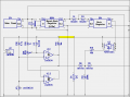
Here is version A4 of the schematic. The changes since version A3 are the addition of 100Ω values to R5-R14, the changing of R1 from 13k to 43k, R2 from 24k to 130k, and the addition of D7 between pins 7 and 6 of U1.
I'll revise it again when necessary, but for now, it's the latest.
Thanks for all the advise guys. Sorry I was tired after assembling the circuit till 4:30am and troubleshoot only awhile and post the picture for you guys to check. The LED circuit alone is working except the charging circuit.
But I do notice the following when I connect:
1: The battery without solar panel, U2 got pretty hot within 3 -4 seconds and I disconnect it from further testing and measuring. LED circuit did not light up
2: Connect solar panel without battery, the LED circuit lights up but Q4 got pretty hot after 3- 4 seconds.
I wanted to try connect both battery and solar panel but worry it will burn some components after a few second.
bertus said:
Hello,
What part is not working?
Or is nothing working?
Bertus
The LED circuit is working but the solar charging circuit is not.
Bernard said:
I'm not great at troubleshooting from pictures, but as start, find no VCC @ 555-8, no D1[ now D7 ? ] & cannot find Q2. Seperate LED ckt from rest & use battery or 12V powersupply to trouble shoot LED ckt. We'll check each function seperatly.Bernard
555 pin 8 was connected before I took the photo as I am trying to troubleshoot and forget to connect back after. There is no D7 yesterday before the schematic was updated.
tracecom said:
I don't see any power on pin 8 of the 555. With your DMM, check there and across pins 4 and 8 of both LM393 chips.
tracecom
I connected both solar panel and battery, seem like those component are not so hot like just now but are still hot. Is that behavior normal? Do I need to have heatsink for all the FDS9435A, LM393 and LM336?
I also notice that when cloud pass by, the LED circuit also turn off and battery did not supply power to light up the circuit.
I measured LM393 pin 4 and pin 8, their readings are 2.24V for U2 and 2.25V for U3 when I only connect the solar panel. Once i connect battery, the voltage for U2 went up to 7.8 voltage and U3 become -0.2V. I had to disconnect the battery cause LM336 is burning hot.
I do not know what other I should test but I do not think it is working correctly. Try to check the circuit again but connections seem to be correct.
On the schematic, U2-8, should go to B1-1,+, so A & B will have power, just a short missing line. I think this will change the V readings- it's a start.
On the schematic, U2-8, should go to B1-1,+, so A & B will have power, just a short missing line. I think this will change the V readings- it's a start.
I see, maybe that's the problem. Actually I had wonder why the line was not link eariler, kinda like 2 separate circuit sharing the same ground. Anyway I am in progress of redoing the whole circuit in case of my mistake. I will update you guys in awhile. I am more than half way done to test again.
Okay I have finished assembling and it is 3:35AM now. No sunlight to test yet so I use another 12V battery to act as solar panel and also connected charging battery.
This time the LED circuit light up, the charging circuit do not have any hot components. I check the charging battery but do not think it is being charged as the voltage remain the same after 5 minutes. If I unplug the battery acting as solar panel, the LED circuit will lights off. So maybe something is not right?
Anyway I measured both LM393, U2 have 12.33V and U3 have 12.3V. Pretty much the same and also LM336 is 9.21V.
Also there are 3 VR resistor, do I need to set any specify value on them. Actually what does they affect in the circuit?
Okay I have finished assembling and it is 3:35AM now. No sunlight to test yet so I use another 12V battery to act as solar panel and also connected charging battery.
This time the LED circuit light up, the charging circuit do not have any hot components. I check the charging battery but do not think it is being charged as the voltage remain the same after 5 minutes. If I unplug the battery acting as solar panel, the LED circuit will lights off. So maybe something is not right?
Anyway I measured both LM393, U2 have 12.33V and U3 have 12.3V. Pretty much the same and also LM336 is 9.21V.
Also there are 3 VR resistor, do I need to set any specify value on them. Actually what does they affect in the circuit?
Well, that's progress; at least there's no overheating. The three variable resistors will need to be set; they adjust the changover point for the lighting circuit power, and for the charging circuit.
I might be able to tell you how to adjust them, but I am not certain, so better wait for Bernard, so as to avoid confusion.
Sure we will wait for him on that. Actually I am thinking without the photoresistor how can the circuit knows that it is night time and dont need to power up the circuit until day time again.
Sure we will wait for him on that. Actually I am thinking without the photoresistor how can the circuit knows that it is night time and dont need to power up the circuit until day time again.
I think that it is the voltage level output from the solar cell that indicates night/day/cloudy. R20 is used to adjust that. It won't hurt if you want to try to set it.
OK, let's start with Day / Night. Temporarly disconnect R 19 from TB1-1. Connect a 1k to 10k pot from +12V to ground ; the tap is now a variable V source. Connect tap to top of R 19 & adjust to 4V, V of SP just after sunrise ? Start with R 20 at bottom and increase untill A-1 goes from Hi to Lo. Reconnect R 19. When SP looses light & V falls to maybe 5V , battery picks up the load. SP falls further to 2.49 V, A-1 switches to Hi, disconnecting battery. A-1 sig. is inverted by B, B-7 goes Lo , pulling bottom of R 20 to ground, insuring thar battery stays off untill SP V again rises to 4 V. Again I'm out of time. Be sure that R 28-2 is full positive to keep it from interfearing with D/N adjustments.
What is a tap that you are referring to over here? Top of R19 is which point?
I just don't understand, we had assembled all the needed components in the circuit and also some variable pots, why do we need to go through all the above you had instructed which I do not understand. Can't we just adjust the existing variable pot to the correct settings?
What is a tap that you are referring to over here? Top of R19 is which point?
I just don't understand, we had assembled all the needed components in the circuit and also some variable pots, why do we need to go through all the above you had instructed which I do not understand. Can't we just adjust the existing variable pot to the correct settings?
I am almost finished breadboarding the circuit around U2. Give me a few minutes to try to follow Bernard's instructions, and maybe I'll be able to answer your questions.
Okay, I have U2 working. Here's what Bernard is saying.
1. We need to set the transition point from day to night, and we need to simulate the output from the solar panel.
2. Disconnect the solar panel from the circuit by disconnecting R19 pin 2 from TB1 pin 1.
3. Create a variable voltage source by using a pot of 1k or 5k or 10k; it doesn't matter. Connect one side of the pot to +12 and the other side of the pot to ground. Then the wiper (he calls it the tap) will have a voltage on it somewhere between 0 and 12V. Adjust it until the voltage on the wiper is 4 volts.
4. Connect R19 pin 2 to the pot wiper with 4V on it.
5. Connect you volt meter to U1, pin 1 and get ready to measure the voltage.
6. Adjust R20 until the voltage reads very close to 12V.
7. If the voltage is very low, disconnect the power, and reconnect the power.
8. Now adjust R20 slowly until you see the voltage drop from 12V to almost 1V.
Now, the sensitivity of U2 is adjusted.

 Facebook
 Google
 GitHub
 Linkedin


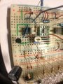
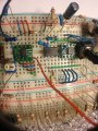
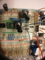
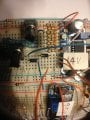


 Anyway I am in progress of redoing the whole circuit in case of my mistake. I will update you guys in awhile. I am more than half way done to test again.



