Need help to light up 8 LEDs with different color

Thread Starter

jenovauh

Joined Jul 4, 2013
246
My piranah, measured, 66mA, 2.6 V. If your red piranahs were mid range- 2.9 V X 3 = 8.7 V add .1V C-E drop = 8.8 V from 9 V supply = .2V / .02 = 10 ohms. Might boost the supply to 10V and re compute.
Hi Benard, I will try that now while the sun is still hot and update in awhile. How can I compute the whole circuit from SP to boost and LED circuit draw how much current? I believe the circuit doesn't draw so much power and trying to see if there is a way to just charge up some battery from the excess. You think it is possible to attached something easy to fit inside this circuit to charge up a battery?
 
Last edited:

Thread Starter

jenovauh

Joined Jul 4, 2013
246
I change the resistor to 10 ohm and adjust boost to output 10V. I can see that the piranha LEDs were slightly brighter than previous.

I try something earlier which I am not sure if it is okay. I created one more LEDs array circuit exactly the same without the 555 timer and 4017 chip. I just attached new resistor from 2N2222(base pin from new LEDs array) to the old LEDs array 555 timer pin3 and pin4. Also connect the positive and negative to the old LED array. It works and both LEDs circuit light up. The brightness of both LEDs array doesnt seem to be affected. I had them running for 4 hours and looks okay to me.

1:If that works, does that mean I can connect a lot more LEDs array in this way?
2:How many LEDs array can I connect in this way?
3:Like I asked on the previous post. How to compute the current draw from the circuit. From the SP to boost+LED current draw?
4:Can design a simple charging circuit when SP output excess current to the circuit? Possible to use a few 3.7V lithium battery?
 

Bernard

Joined Aug 7, 2008
5,784
My understanding now is a 555 is driving 3 2N2222's, which each have 4 strings of 3 red LED's / string, & one string with 2 blue LED's. Each string has a 10 Ω resistor. Measure V across each R to find current for each string. If total is around 300 mA the 12V battery will carry it, with SP's they might be overloaded even at nigh noon. SP power drops off rapidly either side of solar noon, so with your two panels in parallel, a guestimate from a 5 W panel is noon= 2.3 W, 3 PM= 1.88 W, 4 PM = 1.54 W & at 5 PM =.5 W. So maybe 8 hours of solar operation per day. Not much excess power for battery charging.
When checking solar operation, would use the Boost- Buck board.
The 555 should be able to operate up to 15 2N2222's, bit still need about 1.5 A for LED's.
 

Thread Starter

jenovauh

Joined Jul 4, 2013
246
My understanding now is a 555 is driving 3 2N2222's, which each have 4 strings of 3 red LED's / string, & one string with 2 blue LED's. Each string has a 10 Ω resistor. Measure V across each R to find current for each string. If total is around 300 mA the 12V battery will carry it, with SP's they might be overloaded even at nigh noon. SP power drops off rapidly either side of solar noon, so with your two panels in parallel, a guestimate from a 5 W panel is noon= 2.3 W, 3 PM= 1.88 W, 4 PM = 1.54 W & at 5 PM =.5 W. So maybe 8 hours of solar operation per day. Not much excess power for battery charging.
When checking solar operation, would use the Boost- Buck board.
The 555 should be able to operate up to 15 2N2222's, bit still need about 1.5 A for LED's.
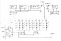
Hu Bernard, base on your last suggestion was only to use two 2N2222 driver to drive 4 strings of LEDs. So right now I am having 2 LED circuit with four 2N2222, one 555 timer and one 4017 counter. The SP is able to produce around 500 -600mA @14v in parallel when the sun are out.

One LEDs circuit with the super bright diode LEDs are using 95 ohms resistors.
Another LEDs circuit with piranha LEDs are using 10 ohms resistors tapping onto the first LEDs circuit 555 timer and 4017 counter.

Hope that clear your thoughts. I know it is confusing as the whole circuit had changes too much over time.
 

Thread Starter

jenovauh

Joined Jul 4, 2013
246
I'll say it is confusing. :) Maybe it's time to restate the project objectives?
Lol hi tracecom, it is very confusing for me too, especially when I am learning and I had google so much to understand. Haha anyway it is all good, learn a lot from Bernard. Still do not understand why the circuit cannot increase the brightness of the LED circuit. Like what is stopping it from that.
 

Thread Starter

jenovauh

Joined Jul 4, 2013
246
I'll say it is confusing. :) Maybe it's time to restate the project objectives?
Okay I think to clear things up and not confused everyone here. The project objectives are as below;

1: To light up 16 Red LEDs, 8 Orange LEDs & 4 Blue LEDs (If=20mA)
2: Using 2 Solar panel in parallel, each is 14V 300mA
3: The circuit are able to pulse the LEDs at 720Hz or higher (http://screwdecaf.cx/sept.html) trying to do a circuit like this one without microprocessor.
4: Able to recharge battery for backup when sunlight is not available
 

Thread Starter

jenovauh

Joined Jul 4, 2013
246
In one of my later posts I suggested removing the 4017,so LED's were either on or off.
Hi Bernard, I track back starting from page 14 to latest page, I never see you ever mentioned to remove 4017 counter, all I can see is using pin 3 and pin 4 for the 1k resistor to the base of the 2N2222 driver. Neither of the drawing are to remove 4017 counter as well. And if I take out 4017, where am I suppose to connect the resistors from the base of 2N2222 to?

Could you please roughly draw the circuit or modify the drawing with the correct circuit you wanted me to follow?
 
Last edited:

Bernard

Joined Aug 7, 2008
5,784
Post 171, " connect both drivers to 555 output".
Remember in post 109, Pg 11, He was using 50 mA red LED's; & total LED power = 4.25 W, total power stated as 1.1W, so duty cycle must be about 25%.
Origionally you had 2 SP's 14V OC , 150 mA SC ea; did you add two more panels to get 600 mA?
As shown on print, the 10 strings draw abot 2 W standing still, will be reducod depending on duty cycle. Other drawing is data from a 5 W SP, 21V OC, modified to approx. match 14V, 600 mA SP. Seems that SP @ 100%, can run LED's untill about 4:30 PM, then battery would make up difference untill nightfall. Night might be a SP V of maybe 4V. Appears to be considerable battery charging current mid day. How to do it? , maybe some real SP data would help.
Note that the timing Rs for 555 have been reversed, 13K top, 24K lower, to give about 60% duty. Change as desired.
 

Attachments

Last edited:

Thread Starter

jenovauh

Joined Jul 4, 2013
246
Post 171, " connect both drivers to 555 output".
Remember in post 109, Pg 11, He was using 50 mA red LED's; & total LED power = 4.25 W, total power stated as 1.1W, so duty cycle must be about 25%.
Origionally you had 2 SP's 14V OC , 150 mA SC ea; did you add two more panels to get 600 mA?
As shown on print, the 10 strings draw abot 2 W standing still, will be reducod depending on duty cycle. Other drawing is data from a 5 W SP, 21V OC, modified to approx. match 14V, 600 mA SP. Seems that SP @ 100%, can run LED's untill about 4:30 PM, then battery would make up difference untill nightfall. Night might be a SP V of maybe 4V. Appears to be considerable battery charging current mid day. How to do it? , maybe some real SP data would help.
Note that the timing Rs for 555 have been reversed, 13K top, 24K lower, to give about 60% duty. Change as desired.
Hi Benards, here are maybe the reason that got confused. :) and thanks a lot for new design schematic.

1:Post 171 - I was thinking that you want me to try oneshot from 555 timer to test the current draw.
2:Post 109 - the circuit is using a lot more LEDs than us and I am not aware that SMT LED are using 50mA. I always thought SMT used very little or 20mA current
3: Yes I used to have 16 piece of 2V 150mA then I purchase 12 more pieces from eBay while I am buying electronic parts to construct the circuit. So I have 28 pieces now and can make 4 array of 14V 150mA and I connect them in parallel.
4: Can I know why we don't need to use the 4017 counter anymore?

A few question on the new schematic
1: The item label B-B and BUCK in the schematic is the same item right?
2: one piece set to output 9.5V and another set to output 10V? If i understand it correctly.
3: Can I replace 1N4002 for 1N4001? As I do not have that part.

I tested the SP last weekend, when the sun shine on them around 12 pm. I am getting about 14.8V to 15.5V and 150 to 170 mA without any load. Direct measurement taken from multimeter.

Note that the timing Rs for 555 have been reversed, 13K top, 24K lower, to give about 60% duty. Change as desired.
Can you roughly explain how to increase or decrease the duty cycle? Also by increase or decreasing duty cycle, will it affect the 720mHz pulse frequency?
 
Last edited:

Bernard

Joined Aug 7, 2008
5,784
4. 4017 demise. What do plants want, twinkling light or full light seperated by full dark & what ratio of light to dark. Using4017 itispart of each , half of the light for half of the time; 555 gives full light with adjustsble ratio of light to dark. Your choice.
1. B-B is boost & buck, B is buck only. I believe that you have one of each.
2. SP & B-B puts out 10 V, 12V battery & B put out 9.5V, just low enough to allow the two sources to be " ORd " via 2 1n4001's io LEDs. As sun lowers, SP output will finally drop out of regulation & V will fall. When both output Vs are equal , both will supply power, a further drop in SP V, battery takes over untill sunset is determined.
3. Any 1n4XXX diode is OK if over 50V, inc. 1N4001.
 

Thread Starter

jenovauh

Joined Jul 4, 2013
246
Supose I forgot to hit "submit". I donot have strength to repeat post, but will post TN. Just getting older, retired in 1986 so you can guess what that makes me- tired.
Hi Bernard, I understand and thank you so much for your time and effort. I really appreciate.

1:Can I know this schematic is to explain on duty cycle or something else? The label D1 value is?

The reason I wants to have pulse frequency at 720mHz is because it is a working theory to fool the plant thinking that it is a full light on them. Which it return we do not need to waste energy. It is okay that my objective is not met. I will continue doing my research to find out how I can make it happen without microchip.
 

Bernard

Joined Aug 7, 2008
5,784
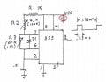
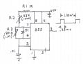
Corrected 555 drawing shows how frequency & duty cycle can set. For high out, C1 charges thru D1, 1N4148, R2, pot or fixed, & R1. R1 is to prevent pin 7 from attempting to short circuit VCC if R2 were at 0 Ω. C1 discharge corrent flows from pin 7, thru R3 , R2,& R1. The fixed values should give about 750 Hz, @ 25 % duty.
Will dig over old posts to see how much of night battery disconnect & charging can be re used.
 

Attachments

Thread Starter

jenovauh

Joined Jul 4, 2013
246
Corrected 555 drawing shows how frequency & duty cycle can set. For high out, C1 charges thru D1, 1N4148, R2, pot or fixed, & R1. R1 is to prevent pin 7 from attempting to short circuit VCC if R2 were at 0 Ω. C1 discharge corrent flows from pin 7, thru R3 , R2,& R1. The fixed values should give about 750 Hz, @ 25 % duty.
Will dig over old posts to see how much of night battery disconnect & charging can be re used.
Hi Bernard, thanks again for the clear diagram and explanation. I will try that out tonight and update the results.
 

Thread Starter

jenovauh

Joined Jul 4, 2013
246
Corrected 555 drawing shows how frequency & duty cycle can set. For high out, C1 charges thru D1, 1N4148, R2, pot or fixed, & R1. R1 is to prevent pin 7 from attempting to short circuit VCC if R2 were at 0 Ω. C1 discharge corrent flows from pin 7, thru R3 , R2,& R1. The fixed values should give about 750 Hz, @ 25 % duty.
Will dig over old posts to see how much of night battery disconnect & charging can be re used.
Hi Bernard, while construction the circuit I realize that is a no value capacitor in the drawing. I circled in red in the attached image.
 

Attachments

tracecom

Joined Apr 16, 2010
3,944
Hi Bernard, while construction the circuit I realize that is a no value capacitor in the drawing. I circled in red in the attached image.
it should be 100nF (.1uF,) and it should be physically located from pin 1 to pin 8 of the 555, as close to the pins as practical.

Just two more posts to go: maybe one for Bernard and one for jenovauh. :D
 

bertus

Joined Apr 5, 2008
22,960
Hello,

For a 555 it is even better to use a 100 nF and a 1 to 10 μF parallel between the pins 1 and 8.
The 555 can produce harsh pulses on the power supply without then.

Bertus
 

Thread Starter

jenovauh

Joined Jul 4, 2013
246
For a 555 it is even better to use a 100 nF and a 1 to 10 μF parallel between the pins 1 and 8.
The 555 can produce harsh pulses on the power supply without then.
Bertus
Hi Bertus, does the positive and negative pin of the capacitor matter? My 1 and 10 uF are electrolytic capacitor. And how do I place them parallel between pin 1 and pin 8 of 555? Care to have a drawing to show layout?

Okay thanks guy. I will check them on the scope to see the differences between capacitor size and update here
 
Last edited:
Top