Need help to light up 8 LEDs with different color

Bernard

Joined Aug 7, 2008
5,784
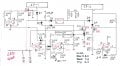
Hot R: What happens if we put a 47Ω resistor across a 9V battery? [9 X 9 ]/47=1.7 W into 1W R = hot. A SP is not the same as a battery as it has much more internal resistance. The ckt is dooing exactly what it is suposed to do, draw enough current from SP to keep output at 9V. I believe I have said all of this before.
I looked up 1N4148 ans see 200 mA, so should be OK for all diode positions.
I see another error; top of R2 should go to SP. While here will explain Day-Night. As light decreases, SP V falls as it still has a light load, R4, V now under 9V so SP is isolated from boost by D1. LEDs now running only on battery. When desired level of darkness , set by R3, is reached, U1 out switches from lo to high. D5 conducts, putting a high on U2-5 which is greater than 2.5V ref. so U2 out goes from lo to hi, shutting off U5, disconnecting battery. This is a verry confusing ckt to me also. I paused to take another look at why the 9V battery-- was a leftover from prev modification & is not needed; remove 9 v battery & tie loose end of R11 to U5-S
 

Attachments

Last edited:

Thread Starter

jenovauh

Joined Jul 4, 2013
246
Hot R: What happens if we put a 47Ω resistor across a 9V battery? [9 X 9 ]/47=1.7 W into 1W R = hot. A SP is not the same as a battery as it has much more internal resistance. The ckt is dooing exactly what it is suposed to do, draw enough current from SP to keep output at 9V. I believe I have said all of this before.
I looked up 1N4148 ans see 200 mA, so should be OK for all diode positions.
I see another error; top of R2 should go to SP. While here will explain Day-Night. As light decreases, SP V falls as it still has a light load, R4, V now under 9V so SP is isolated from boost by D1. LEDs now running only on battery. When desired level of darkness , set by R3, is reached, U1 out switches from lo to high. D5 conducts, putting a high on U2-5 which is greater than 2.5V ref. so U2 out goes from lo to hi, shutting off U5, disconnecting battery. This is a verry confusing ckt to me also. I paused to take another look at why the 9V battery-- was a leftover from prev modification & is not needed; remove 9 v battery & tie loose end of R11 to U5-S
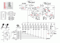
Okay sure and thanks Benard, I will work on that and raise question when I am confuse again. :) Will draw the complete schematic again and let you check. Only the boost is not done right?
 

Thread Starter

jenovauh

Joined Jul 4, 2013
246
Hot R: What happens if we put a 47Ω resistor across a 9V battery? [9 X 9 ]/47=1.7 W into 1W R = hot. A SP is not the same as a battery as it has much more internal resistance. The ckt is dooing exactly what it is suposed to do, draw enough current from SP to keep output at 9V. I believe I have said all of this before.
I looked up 1N4148 ans see 200 mA, so should be OK for all diode positions.
I see another error; top of R2 should go to SP. While here will explain Day-Night. As light decreases, SP V falls as it still has a light load, R4, V now under 9V so SP is isolated from boost by D1. LEDs now running only on battery. When desired level of darkness , set by R3, is reached, U1 out switches from lo to high. D5 conducts, putting a high on U2-5 which is greater than 2.5V ref. so U2 out goes from lo to hi, shutting off U5, disconnecting battery. This is a verry confusing ckt to me also. I paused to take another look at why the 9V battery-- was a leftover from prev modification & is not needed; remove 9 v battery & tie loose end of R11 to U5-S
Hi Benard, can you take a close look at the schematic again to make sure all the links are correct as per your design? I had tried to follow and redraw all the necessary changes. Thanks.
 

Attachments

Bernard

Joined Aug 7, 2008
5,784
Looks good. 'Think R11 could drop from 1M to 100k. In adjusting charge cut off & re connect, R15 is about 410k to re connect charging at 7.3V, but as said in post # 138 use a pot then can sub a fixed value. Might put 2.5V reg on LED drawing. LM336Z pinout shown on post #138 and is direct replacement for red LED used as temp. V reg.
 

Thread Starter

jenovauh

Joined Jul 4, 2013
246
Looks good. 'Think R11 could drop from 1M to 100k. In adjusting charge cut off & re connect, R15 is about 410k to re connect charging at 7.3V, but as said in post # 138 use a pot then can sub a fixed value. Might put 2.5V reg on LED drawing. LM336Z pinout shown on post #138 and is direct replacement for red LED used as temp. V reg.
Yes I forget to draw that one on the circuit. Anyway that component have not arrive yet. Was a bit confuse with the replacement. Will take a closer on on your previous post #138 and update it.
 

Bernard

Joined Aug 7, 2008
5,784
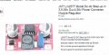
What a deal, I see no reason that it will not work, might want to pickup the Lipo Battery Meter for only $ 1.88.
It uses the same IC, LM2577S, different package that I was looking for.
 
Last edited:

Thread Starter

jenovauh

Joined Jul 4, 2013
246
What a deal, I see no reason that it will not work, might want to pickup the Lipo Battery Meter for only $ 1.88.
It uses the same IC, LM2577S, different package that I was looking for.
Benard are you referring to this Lipo Battery Meter? Assuming if I get the
DC-DC buck converter and the Lipo Battery Meter. How am I suppose to attached them into your design?
 

Bernard

Joined Aug 7, 2008
5,784
The boost is a direct drop in, on drawing , boost - goes to D8 cathode, + to to D3 anode, & all grounds are common. Meter is optional if you have good digital meter. If you buy- post instruction sheet showing pin assignments.
 

Thread Starter

jenovauh

Joined Jul 4, 2013
246
The boost is a direct drop in, on drawing , boost - goes to D8 cathode, + to to D3 anode, & all grounds are common. Meter is optional if you have good digital meter. If you buy- post instruction sheet showing pin assignments.
Cannot test anything thing yet as the part which came is wrong by the seller, gonna wait again. :(
 
Last edited:

Thread Starter

jenovauh

Joined Jul 4, 2013
246
Just an update the parts LM336Z-2.5 have not arrive. :(

Anyway Benard, I got the booster you mentioned. I am thinking does the whole circuit itself need to be so complicated? It is too much for a newbie like me to troubleshooting when I try to assemble all together. Just my thought. Thanks again.
 

Bernard

Joined Aug 7, 2008
5,784
For what little light is delivered it seems to me an extreemly complex system, but it seems to answer your requirements. As I suggested before,operate on only solar to see if experiment works, & add battery backup only if necessary. We will stick with you as long as you are willing to try.
 

Thread Starter

jenovauh

Joined Jul 4, 2013
246
For what little light is delivered it seems to me an extreemly complex system, but it seems to answer your requirements. As I suggested before,operate on only solar to see if experiment works, & add battery backup only if necessary. We will stick with you as long as you are willing to try.
Hi Benard, I want to try the light with only solar but without the LM336Z-2.5 I could not right? Correct me if I am wrong. Anyway I had purchased all the parts to experiment and learn. It is an expensive little light circuit lol.
 

Bernard

Joined Aug 7, 2008
5,784
If you go back a few ckts, think we used a LED as the ref in a solar only. Could you list the specs of the boost- buck board? might fave a use in solar only.
 

Thread Starter

jenovauh

Joined Jul 4, 2013
246
If you go back a few ckts, think we used a LED as the ref in a solar only. Could you list the specs of the boost- buck board? might fave a use in solar only.
Hi Benard, I bought 2 type and the specs are below. You can see which is more suitable for my application and how we can mod the circuit to work with this boost.

First type********************
Module Properties: non-isolated Auto Buck-Boost module
Input voltage: 3-35V
Adjustment method: first input the right power (between 3-35V ) then use the multimeter monitor the output voltage and adjust potentiometer (clockwise turn down usually , turn counterclockwise Boost)
Output voltage: 2.25V-30V(Continuously adjustable)
Input Method: IN +Input positive level, IN-Input negative level
Output Method: OUT +Output positive level, OUT-Output negative level

Input 3V, Output 5V, The Max output current 0.3A
Input 5V, Output 13V, The Max output current 0.3A
Input 7.4V, Output 12V, The Max output current 0.5A
Input 10V, Output 12V, The Max output current 0.7A
Input 12V, Output 12V, The Max output current 0.7A
Input 12V, Output 15V, The Max output current 0.6A
Input 12V, Output 19V, The Max output current 0.5A
Input 15V, Output 19V, The Max output current 0.5A
Input 24V, Output 12V, The Max output current 1.7A

Second type:
Module Properties: non-isolated step-down (BUCK)
Rectification: non-synchronous rectification
Input voltage: 4V-35V
Output voltage: 1.23V-30V
Output Current: 3A (max)
Conversion efficiency: 92% (the highest)
Switching frequency: 150KHz
Output ripple: 30mV (max)
Load Regulation: ± 0.5%
Voltage Regulation: ± 2.5%
 

Bernard

Joined Aug 7, 2008
5,784
Let's try a test of #1, connect both SPs in parallel, then connect B-B to SPs + to +, - to - , & then a 100Ω, 1W as a load on output of B-B. Any combinatoin of resistors to come close to 100. Adjust pot for 9V output.
Might connect a red LED & 330 Ω across output as a visual monitor & see how much variation of light will still give a usefull output.
If using pulsed light based on post 147, note that light never goes out, just shanges color, so might double up, or tripple up LED strings & then use alternating outputs on 4017. So output 0, pin 3 would go to a 1k R then to base of 2N2222, collector would have 3 strings of LEDs; skip out 1,pin2, & connect next driver to pin 4, 3 strings, pin 10- 2
strings, pin 5- 2 strings, & pin6 to reset.
If output V holds at 9 V or lower, replace 100Ω with LED ckt. & grow some plants.
Drop the shunt regulator, LM393 & all ascociated parts.
 
Last edited:

Thread Starter

jenovauh

Joined Jul 4, 2013
246
Let's try a test of #1, connect both SPs in parallel, then connect B-B to SPs + to +, - to - , & then a 100Ω, 1W as a load on output of B-B. Any combinatoin of resistors to come close to 100. Adjust pot for 9V output.
Might connect a red LED & 330 Ω across output as a visual monitor & see how much variation of light will still give a usefull output.
If using pulsed light based on post 147, note that light never goes out, just shanges color, so might double up, or tripple up LED strings & then use alternating outputs on 4017. So output 0, pin 3 would go to a 1k R then to base of 2N2222, collector would have 3 strings of LEDs; skip out 1,pin2, & connect next driver to pin 4, 3 strings, pin 10- 2
strings, pin 5- 2 strings, & pin6 to reset.
If output V holds at 9 V or lower, replace 100Ω with LED ckt. & grow some plants.
Drop the shunt regulator, LM393 & all ascociated parts.
Hi Benard, thanks for the suggestion. I am wondering if you could edit the previous drawing I had on the changes. I am confused lol.
 
Top