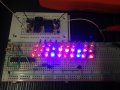
Hi Benard, I have some question after reading post #157 and tally with the drawing on post #159. I notice the drawing only have 3 strings of LEDs but you mentioned 4 strings of LEDs in post #157. Anyway with the picture, I had already understand what you are trying to tell me on post #157. I just follow the instruction on post #157 and use the drawing as a guide.
And I did the following test.
1: The test load did not work on raining day. So I use a 12V SLA battery and connect to the buck converter, set output to 9V. Connect the test circuit, red LED lighted but the 100 ohm 1W resistor got pretty hot after like 10 seconds. I change to 270 ohm 1W resistor and it become slightly warm. Will try the Solar panel when it is sunny here again.
2: I use a 12V SLA battery and connect to the buck converter and set to 9V output then connect the actual LED circuit. All 4 strings of LEDs are lighted and components seem to be cool.
Last of all, can I know is the last drawing circuit the high pulse circuit that I asked for? And how can I check the pulse rate. I have access to a desk oscilloscope to test it. The brightness of the LEDs does not seem to be full brightness of 20mA, I try to measure the circuit drawn by the LEDs but it does not show anything on the multimeter. No idea what's wrong and measure with 3 different multimeter, all showing nothing. How can I increase the brightness?
Success on test 1 & 2, the B-B board does its job. Plant sees 50% duty, so light will not be verry bright, post 159, but much more light power than with 10 LED strings. Might evev consider using only 2 drivers, 5 strings each. so to see or measure LED current, we need to stop clocking by returning 4017 inhibit, pin 13 to +V, or convert 555 to one-shot, or disconnect clock, p-14, tie it to ground thru 10k. them touch p-14 momentarily to+v to manually step. Fpr new 750 Hz, change 555-12k to 24K. 555-3 should measure .00066 s on scope.
Success on test 1 & 2, the B-B board does its job. Plant sees 50% duty, so light will not be verry bright, post 159, but much more light power than with 10 LED strings. Might evev consider using only 2 drivers, 5 strings each. so to see or measure LED current, we need to stop clocking by returning 4017 inhibit, pin 13 to +V, or convert 555 to one-shot, or disconnect clock, p-14, tie it to ground thru 10k. them touch p-14 momentarily to+v to manually step. Fpr new 750 Hz, change 555-12k to 24K. 555-3 should measure .00066 s on scope.
1: I will try the 2 driver and 5 strings each. Meaning only 2 piece of 2N2222 transistor right?
2: We need to stop clocking by returning 4017 inhibit, pin 13 to +V. Can I know pin 13 to +V meaning which +V?
3: Or convert 555 to one-shot?
4: Or disconnect clock. p 14 tie to ground thru 10k (I understand this) then touch p 14 momentarily to +V to manually step (totally lost on this sentence)
5: For new 750 Hz, change 555 12k to 24K (meaning 555 pin 7 to pin 8 right?)
Am I suppose to combine all these suggestion together? My intention is to have over 750 Hz pulse and full brightness if possible. Are we able to achieve that with this circuit. Or what do you suggest the best to try on? Thanks again Bernard.
I did the following adjustment which I understood.
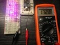
I change the 12K resistor to 24K for 555 pin 7 to pin 8. Using only 2 X 2N2222 transistor, 1 to 4017 pin 3 and 1 to 4017 pin 4. I measured the LED is only drawing 0.46 mA. I measure the output from the buck to LEDs circuit is drawing 1.72 mA.
Measurements while running are almost meaningless. Temporarily connect 555 as OS. Add a large cap, 1μF or greator, in parallel with .01,C1, to stretch the output pulse so as to eliminate SW bounce. V across 120 Ω should be around 2.4V for 20 mA. Also check 2N2222 collector V, about .1V? Try moving reset from p-5 to p-10. Looks good.
Measurements while running are almost meaningless. Temporarily connect 555 as OS. Add a large cap, 1μF or greator, in parallel with .01,C1, to stretch the output pulse so as to eliminate SW bounce. V across 120 Ω should be around 2.4V for 20 mA. Also check 2N2222 collector V, about .1V? Try moving reset from p-5 to p-10. Looks good.
1: The 555 timer drawing is just to test the actually output voltage and current right?
2: I will change 4017 output to pin 3 and pin 4 for 2N2222 transistor and pin 10 to reset.
3: What does Temporarily connect 555 as OS, I dont understand "OS"
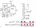
4: I have 2 red circle on the drawing that I dont quite understand, can you explain further?
1 & 3. The 555 is temporarly modified to make a OS, one shot, one SW closure = one putput pulse, which allows the 4017 to be advanced manually one step at a time to allow static measurements.
2. 4017 pin 3 & 4 change was reported in post 165. The colored squares represents a timing diagram to show light & dark. Top is p 3,4 , reset on p-5 which may allow too much off time. Bottom shows result of moving reset to p-10. A red square represents 5 strings of ON LED's. P-3,"0" is first 5, P-4 "2" is second group of 5 strings. Each square represents .66 ms, so 2 squares represents one complete cycle , 1.33 ms or 750 Hz
3. Second circled item is a NO PB SW, normally open push button switch,
which is debounced by 555. If a SW is used directly on 4017 input, one push may advance count several steps. Bouncing may last up to 20ms, so 555 should be set for a much longer time.
I had done item number 2 yesterday so far it is running okay before i went out to work. I will continue to test on item number 1 and 3 after work to check the actually current draw and voltage as mention. Will update you later. Thank you.
I try to follow the picture to add 1M resistor and the 10uF capacitor (I dont have 1uF), I have no idea where to tap to check the voltage and current draw. The LEDs array are flashing between the two 2N2222 driver.
Can you mark on the drawing where to tap the 2 point to measure the current and also mark the 2 point to tap to check the voltage. Do I need to disconnect 555 Pin-3 to 4017 when measuring?
Can you also advise how can I increase the brightness of the LEDs array. Thanks.
Sorry, looks like I skipped a step: The connection between 555-2 & 555-6 needs to be temporarly removed to convert from oscillator to OS.
To measure LED current, measure V across one of the 120 Ω resistors, then compute I, I= V/R. Also measure collector V, to be sure 2N2222 is fully turned on.
Each group of 5 strings is on 1/4 of time, 25% duty. Next try would be to connect both drivers to 555 output, then you can pick any duty cycle. Also add a 100 μF, or what ever you have from SP+ to ground, the 12V battery probably does'nt care that it is i pulsed load.
Sorry, looks like I skipped a step: The connection between 555-2 & 555-6 needs to be temporarly removed to convert from oscillator to OS.
To measure LED current, measure V across one of the 120 Ω resistors, then compute I, I= V/R. Also measure collector V, to be sure 2N2222 is fully turned on.
Each group of 5 strings is on 1/4 of time, 25% duty. Next try would be to connect both drivers to 555 output, then you can pick any duty cycle. Also add a 100 μF, or what ever you have from SP+ to ground, the 12V battery probably does'nt care that it is i pulsed load.
I see, no wonder the circuit become flashing. I will try to disconnect 555-2 and 6 when I am home later and update you. I am only able to test SP on weekends.
Hi Benard, I test the voltage across the 120 ohm resistor to the LEDs circuit is 1.9V, so after computing the current draw is 15.83mA. And the 2N2222 collector is 0.05V. I am using 12V SLA battery to do the test.
Anyway Bernard can you advise on how I can increase the LEDs brightness for this circuit? Or anything we need to do to improve the circuit?
For the red string measuring 1.9 V, the Vf seems to be 2.36 V, a little higher than predicted, so 120 should now be 95Ω. Do not think it will greatly increase brightness. If you go to higher power LEDs, you will need more SP power.
That's mean the brightness of the circuit is pretty much that bright? Anything can be change to increase it? Higher power LEDs will be those 1W LED bead, are you referring to that? Those need a lot more power.
Currently the brightness on the LED diode are about 30-40% lighted. It that suppose to be the actual brightness for the design?
Once that you have adjusted the resistors for 20 mA, there is not much else you can do, except to increase duty cycle, or add more LEDs, but then you'll be running out of SP power.
Once that you have adjusted the resistors for 20 mA, there is not much else you can do, except to increase duty cycle, or add more LEDs, but then you'll be running out of SP power.
Although I had adjusted the resistors to 20mA but the LEDs doesnt seem to be power at that brightness. I replace my 5mm LEDs diode with piranha superflux LEDs. They still look not bright lol. How to increase the duty cycle and also adding more LEDs in term of more strings and drivers? SP power can be increase when needed so that is really not an issue.
The spec are as below. What about your spec cause mine doesnt look so bright in this circuit. But If I try one piece with 20mA current, it is very bright.
My piranah, measured, 66mA, 2.6 V. If your red piranahs were mid range- 2.9 V X 3 = 8.7 V add .1V C-E drop = 8.8 V from 9 V supply = .2V / .02 = 10 ohms. Might boost the supply to 10V and re compute.

 Facebook
 Google
 GitHub
 Linkedin


 My intention is to have over 750 Hz pulse and full brightness if possible. Are we able to achieve that with this circuit. Or what do you suggest the best to try on? Thanks again Bernard.