Need help repairing Allen & Heath Xone:DB4 mixer

Thread Starter

DibElias

Joined Feb 28, 2023
129
One possibility is that there is a reference voltage from the CS5368 that has to go to all the 5532JRC to set the DC bias voltage.
I’ll place the purchase tomorrow. It’ll be some time before I get back here.

I saw another person have an issue with his DB4 mixer… it sounds like this mixer is just not built with decent quality components.

Thank you for being patient with my level of knowledge on pcbs.
 

Thread Starter

DibElias

Joined Feb 28, 2023
129
We did not have a chance to discuss solder and soldering techniques.
It would help me if I saw a photo of your soldering iron station or at least the make and model.

You need some solder wick and a flux dispenser.
You should use both to clean up any pads before reinstalling any component. Also do this to make sure that there are no solder bridges.

You should avoid using lead-free solder. Use 63/37 Sn/Pb solder with a rosin core.

If you have questions about the soldering technique, don't be afraid to ask.

  1. This is the soldering technique I looked up for the IC installation.
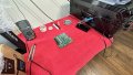
  2. My soldering station is my ceramic kitchen island, cleaned and cleared from biohazards.
  3. I have this soldering kit I purchased off amazon. What sucks about the lead that came with it is that it mostly smokes and evaporates.
  4. I currently dial the solder to 400°C. Is this favorable? My max option is 450°C.
 

MrChips

Joined Oct 2, 2009
35,024
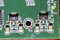
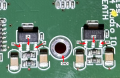
After you get the mixer working and before putting it all back together again, it would be a good idea to record the voltages at the two LD1117AG 3-terminal regulators.

Measure the voltages at the three pins 1, 2, and 3 with respect to GND on each of the two regulators.
Set the DMM to 20VDC. BLACK lead goes to GND.

Allen&Heath XONE DB4 004-068 LD1117AG.jpg
 

MrChips

Joined Oct 2, 2009
35,024
Waiting on the Cirrus Logic A/D chip to arrive. Eta a few more days.

By the way, how were you able to identify the faulty small capacitor was a 100nf?I have an assortment and they all look the same.
I did not. I just assumed that 100nF is a common value for supply rail decoupling.
 

Thread Starter

DibElias

Joined Feb 28, 2023
129
After you get the mixer working and before putting it all back together again, it would be a good idea to record the voltages at the two LD1117AG 3-terminal regulators.

Measure the voltages at the three pins 1, 2, and 3 with respect to GND on each of the two regulators.
Set the DMM to 20VDC. BLACK lead goes to GND.

View attachment 289326
1678860286053.png
Update:
I connected everything but the logic and turned the PCB on. This time there was no smoke or shorts seen on the board. Also the hot spots are gone.

I tested the voltage shown above. I am working on adding the logic chip next.

Results
1A = 3.85V
2A = 5.12V
3A = 6.90V

1B = 3.84V
2B = 5.10V
3B = 6.90V
 

Thread Starter

DibElias

Joined Feb 28, 2023
129
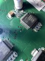
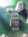
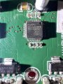
I soldered the Logic IC back on and did a continuity check from pin to pin making sure results matched the other identical IC on the board.
I powered the pcb and left it on for some time and observed no hot spots.
Remeasured the voltages across the last check you suggested read similar results.
1A = 3.85V
2A = 5.12V
3A = 6.90V

1B = 3.84V
2B = 5.10V
3B = 6.90V

I hooked everything back up and tested for analog output and I got nothing. However, this time, I can see the channel leds flashing up while inserting the RCA indicating something improved just not fully since no audio output.
Through the headphones, I can hear a much smoother static that before.

I’ll open it back up tomorrow and take close ups to all the replaced components. I’m sure though the terminals are carefully connected and confirmed no shorts between them post the job.

I wonder where from here!
 

Attachments

MrChips

Joined Oct 2, 2009
35,024
Measure the voltage on both sides of the 10R0 resistors to make sure that the power supply rails are at the proper operating voltages.

Your next step would be to input music source into the analog inputs (RCA jacks).
Use your oscilloscope to trace the signals on the outputs of the 5532 opamps, pin-1 and pin-7.
 

Thread Starter

DibElias

Joined Feb 28, 2023
129
Measure the voltage on both sides of the 10R0 resistors to make sure that the power supply rails are at the proper operating voltages.

Your next step would be to input music source into the analog inputs (RCA jacks).
Use your oscilloscope to trace the signals on the outputs of the 5532 opamps, pin-1 and pin-7.
I’ll need to figure out which is a good signal and which is not.
What about checking opamp terminal voltages? Can that yield any clues?
 

MrChips

Joined Oct 2, 2009
35,024
The purpose of the oscilloscope test is to check that the signal is getting through to that stage.
At the same time you can see the actual DC voltages to make sure that they make sense for that stage of the system.

What the oscilloscope display will show you are:

1) signal amplitude (peak-to-peak)
2) minimum and maximum signal voltage
3) average DC voltage (i.e. any DC bias)
4) possible clipping on low and high peaks

The signal amplitude will depend on the amplification and of course the music content and volume level setting.

Here is a sample view of music content on an oscilloscope.


Thread Starter

DibElias

Joined Feb 28, 2023
129
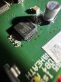
Update: I have not done any signal tracking yet. I was attempting to do so and discovered that both logic chips now are heating up. There are also some op amps warming up. I would say 7/10 hot.
They were not heating up before. The difference in setup now is I have all pcbs connected.

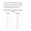
these are the caps I changed. They measure 11.25 uf however have a letter G instead of V with a straight line. Is that okay?
 

Attachments

Thread Starter

DibElias

Joined Feb 28, 2023
129
second update:
I have sign of life.
I turned on playback analog in CH4 and it output audio however, it is not clear audio.

it is distinctly audible just not clear. There’s static in the mix. The led mark on the mixer is in constant peak mode.

i tried all four channels they all output audio.
This means the Audio IO pcb is getting signal
from the connector pcb.
With the logics being hot now and other hot spots in opamp area, I think something is still not right in the audio io pcb.
 

Attachments

Thread Starter

DibElias

Joined Feb 28, 2023
129
I installed back on the original caps, the issue did not go away. Something continues to cause a short circuit, causing both Sirrus Logic chips to considerably heat up.

Is it possible that one of the opamps is not functioning correctly?
Can I confirm without turning the pcb on?
 

Thread Starter

DibElias

Joined Feb 28, 2023
129
I have an interesting find :rolleyes:

The sirrus logic ADC chips only heat up when monitor PCB is connected. I removed and attached its connector to the motherboard and confirmed that this is the case.

I then took voltage readings of the +/- 15 volt pins coming from motherboard to audio IO with monitor pcb connected then disconnected.
Without it connected, the main voltage rails into audio IO read +/- 15 V (to spec).
When I connect monitor pcb they read +/- 19.2 V instead.

what are your thoughts on this finding?


1679016636587.png
 
Top