Need help repairing Allen & Heath Xone:DB4 mixer

MrChips

Joined Oct 2, 2009
35,030
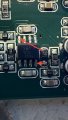
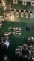
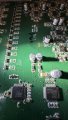
Before you do that. Check for strands of something around that bad chip. I can see something in the photo.
Make sure there are no stray pieces of solder or metal shards hanging around.
 

Thread Starter

DibElias

Joined Feb 28, 2023
129
FYI, when I measure the resistance across the other larger caps I removed, they measure OL. Does that mean anything?
 

MrChips

Joined Oct 2, 2009
35,030
FYI, when I measure the resistance across the other larger caps I removed, they measure OL. Does that mean anything?
It means that there is no measurable short under these test conditions.
I intentionally did not say to install the capacitors. We want to keep it out of the equation until this next test is completed.
 

Thread Starter

DibElias

Joined Feb 28, 2023
129
Ok, I'll leave them off the board, install new 10R0s, and power the board.
Ill check for strands.
Be right back.
 

MrChips

Joined Oct 2, 2009
35,030
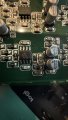
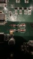
Check the solder pads where those large caps should go. Looks like a short between two pads.
Clean up with solder wick
 

MrChips

Joined Oct 2, 2009
35,030
Your next task, which would be your proof of successful progress, is to measure the voltage on each side of the two 10R0 resistors with the BLACK lead on the mounting hole (GND). Four measurements in total with the DMM set to 20VDC.
 

MrChips

Joined Oct 2, 2009
35,030
Ok. There is one more task before we take a break for the night.
Install the two large capacitors and test the voltages again.
Before you apply power, let me examine your handy work before I give the ok. I need to check that you have soldered the capacitors with the correct polarity. Remember, the black mark on the capacitor is the negative polarity.

When this part is over, you need to buy a 100nF chip capacitor and a new CS5368 chip.
You can install these and repeat the same voltage tests on the two 10R0 resistors.

The final verdict is one 10-cent capacitor gave you this big headache.
We don't know what caused this capacitor to go bad. It is not a common failure mode.
We don't know if the CS5368 is damaged or not. At this point it would be wise to install a new one.
 

Thread Starter

DibElias

Joined Feb 28, 2023
129
Ok. There is one more task before we take a break for the night.
Install the two large capacitors and test the voltages again.
Before you apply power, let me examine your handy work before I give the ok. I need to check that you have soldered the capacitors with the correct polarity. Remember, the black mark on the capacitor is the negative polarity.

When this part is over, you need to buy a 100nF chip capacitor and a new CS5368 chip.
You can install these and repeat the same voltage tests on the two 10R0 resistors.
ok brb
 

MrChips

Joined Oct 2, 2009
35,030
Looks good. You are good to go.

When this part is over, you need to buy a 100nF chip capacitor and a new CS5368 chip.
You can install these and repeat the same voltage tests on the two 10R0 resistors.

The final verdict is one 10-cent capacitor gave you this big headache.
We don't know what caused this capacitor to go bad. It is not a common failure mode.
We don't know if the CS5368 is damaged or not. At this point it would be wise to install a new one.

Install the replacement capacitor and the new CS5368.
Double check and make sure that there are no shorts between pins when you solder the new CS5368.
If you need tips on how to do this don't be afraid to ask.
(The board will still work without the capacitor.)

Good luck on wrapping up this project.
 

Thread Starter

DibElias

Joined Feb 28, 2023
129
Looks good. You are good to go.

When this part is over, you need to buy a 100nF chip capacitor and a new CS5368 chip.
You can install these and repeat the same voltage tests on the two 10R0 resistors.

The final verdict is one 10-cent capacitor gave you this big headache.
We don't know what caused this capacitor to go bad. It is not a common failure mode.
We don't know if the CS5368 is damaged or not. At this point it would be wise to install a new one.

Install the replacement capacitor and the new CS5368.
Double check and make sure that there are no shorts between pins when you solder the new CS5368.
If you need tips on how to do this don't be afraid to ask.
(The board will still work without the capacitor.)

Good luck on wrapping up this project.
i powered back up and read the proper voltages at the 10R0 resistors, same as shared before this last step.

the only qusstion I have, is why are the JRCs warming up now when not before. They all have about the same temperature.

notes on the rest.
 

MrChips

Joined Oct 2, 2009
35,030
i powered back up and read the proper voltages at the 10R0 resistors, same as shared before this last step.

the only qusstion I have, is why are the JRCs warming up now when not before. They all have about the same temperature.

notes on the rest.
One possibility is that there is a reference voltage from the CS5368 that has to go to all the 5532JRC to set the DC bias voltage.
 
Top